BA_373-E45_05_DEF_MJ_2119
21 | 36W. Baelz & Sohn GmbH & Co. · Koepffstrasse 5 · 74076 Heilbronn · Germany · www.baelz.de Seite | Page
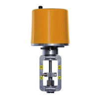
Motorized Linear Actuator baelz 373-E45
Fig. 9: Wiring diagram with digital positioner baelz 7020A
8.3.2 Allocation of connection terminals
Terminal Allocation Notes
2, 3
supplyterminals Seewiringdiagramfor
correct allocation.
4, 5, 12, 14
Canbeallocatedtoan
overridingexternalcontrol
system(freezeprotection,
excessivetemperatures).
Forexternalcontrol,the
N↔Sswitchmustbeset
to„S“(safetymode).
20, 22
Digitalinputforaswitch
usedtoselectbetweentwo
conditions,
e.g.„open/closed“or
„summer/winter“.
23, 24, 25,
26
Analogueoutputposition
indicaterusingvoltageand
/orcurrent.
Analogueoutputs
canbeconnected
simultaneously.
38, 39, 40
Connectionterminalsfor
Modbus
91, 92, 93
Connectionterminalsfor
potentiometer
U, 0, I
Inputsetpointvaluefor
valveposition
IMPORTANT!Positionof
DIPswitch1,seesection
8.4
E1, E2, E3,
E4, E5, E6
Terminalsfor2digital
outputs
IMPORTANT!Positionof
DIPswitches5&6,see
section 8.4
97, 98, 99
Connectionterminalsfor
motor
Ex-workswiringvaries
accordingtotypeof
actuator