EasyManua.ls Logo

Balluff BNI EIP-104-105-Z015 - Ethernet; Function Indicators; Module Status; Port

Balluff BNI EIP-104-105-Z015
20 pages
To Next Page IconTo Next Page
To Previous Page IconTo Previous Page
Loading...
www.balluff.com
9
4 Technical data
4.5. Ethernet
Ethernet IP port
1 x 10Base-/100Base-Tx
Connection for Ethernet IP port
M12, D-coded
Cable types per IEEE 802.3
Shielded twisted pair min. STP CAT 5/ STP CAT 5e
Data transmission rate
10/100 Mbit/s
Max. cable length
100 m
Flow control
Half Duplex/Full Duplex (IEEE 802.33x-Pause)
4.6. Function
indicators
Module status
LED
Status
Function
UA
green
Output power OK
red
Low Output power (< 18V)
US
green
Input power OK
red
Low Input power (<18V)
Mod
green flashing
Wrong or no configuration on module
green
Modul operating
red flashing
Fixed busclock is not possible
red-green flashing
Initial sequence
Net
off
Module got no IP address
green flashing
Module got IP, but no connection could be established
green
Connection established
red flashing
Connection timeout
red-green flashing
Initial sequence
100
off
Bus clock: 10 Mbit/s
yellow
Bus clock: 100 Mbit/s
LNK
green
Data transfer
Port
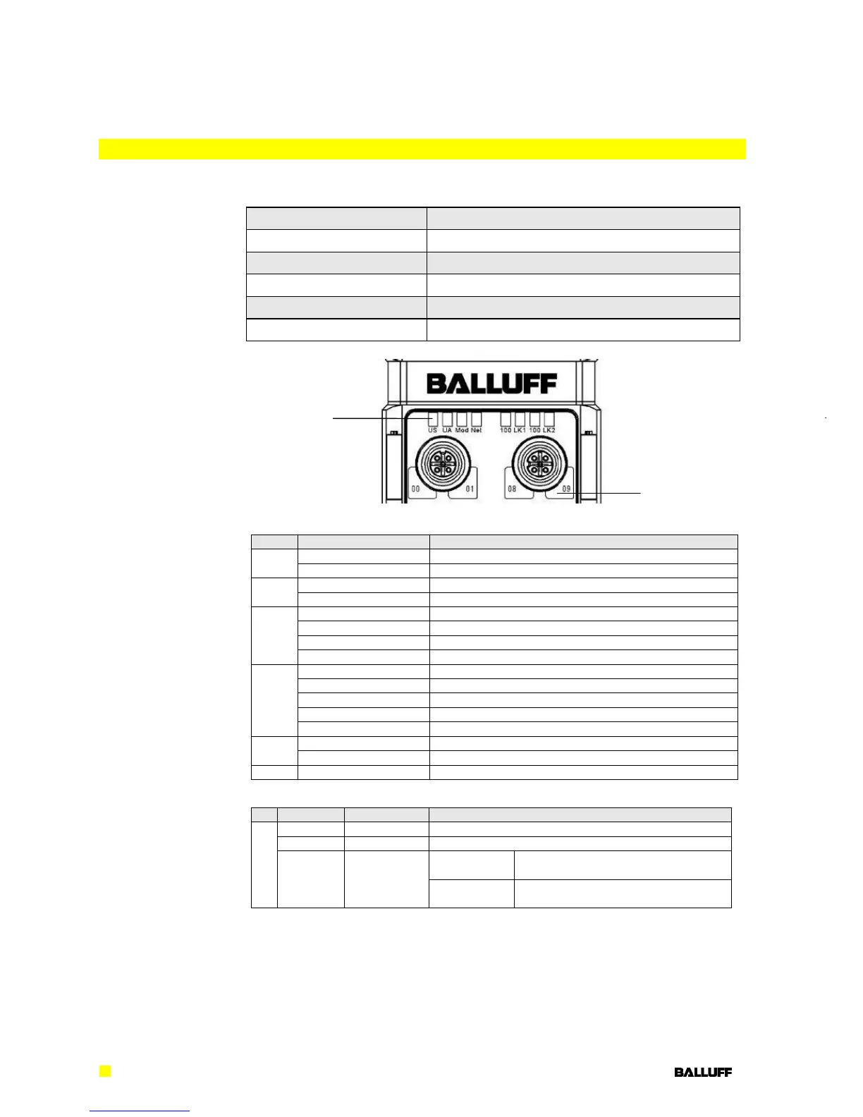
Each Port has two two-colour LEDs to indidcate the I/O-States.
Status
Function
Description
I/O Port
off
I/O-State
State of the Input or Output Pin is 0
yellow
I/O-State
State of the Input or Output Pin is 1
red
Short-circuit
single LED:
Short-circuit on dedicated Pin (only if
this pin is used as an output)
both LEDs:
Short-circuit between Pin 1 and 3 or
Short-circuit on both output pins
Status-LEDs
Port LEDs
Port-Leds

Related product manuals