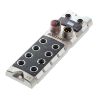
The BNI EIP-… serves as a decentralized input and output module for connecting to an
EtherNet/IP™ network.
1.2. Structure of the
guide
The guide is organized so that the chapters build on one another.
Chapter 2: Basic safety information.
Chapter 3: The main steps for installing the device.
Chapter 4: Technical data for the device
Chapter 5: Integration
Chapter 6: Process data
Chapter 7: Display
Chapter 8: Webserver
Chapter 9:Appendix
1.3. Typographical
Conventions
The following typographical conventions are used in this Guide.
Enumerations are shown in list form with bullet points.
• Entry 1,
• Entry 2.
Action instructions are indicated by a preceding triangle. The result of an action is indicated
by an arrow.
Action instruction 1.
Action result.
Action instruction 2.
Procedures can also be shown as numbers in brackets.
(1) Step no. 1
(2) Step no. 2
Numbers:
Decimal numbers are shown without additional indicators (e.g. 123),
Hexadecimal numbers are shown with the additional indicator hex (e.g. 00
hex
) or with the
prefix “0x” (e.g. 0x00)
Cross references indicate where additional information on the topic can be found (see
chapter 4 ”Technical Data”).
Note tip
This symbol indicates general notes.
Note
This symbol indicates a security notice which most be observed.
BNI Balluff Network Interface
I Standard input port
EIP EtherNet/IP™
EMC Electromagnetic Compatibility
FE Function ground
O Standard output port

 Loading...