Troubleshooting
Manual Adjustments Disabled
Manual adjustments are disabled when Auto Thresholds are ON. If a manual adjustment is attempted while Auto
Thresholds are ON, the Green display will flash
.
Percent Minimum Difference after TEACH
The Two-Point and Dynamic TEACH methods will flash a % minimum difference on the displays after a PASS or FAIL.
Value PASS/FAIL Description
0 to 99% FAIL The difference of the taught conditions does not meet the required minimum
100 to 300% PASS The difference of the taught conditions just meets/exceeds the required minimum,
minor sensing variables may affect sensing reliability
300 to 600% PASS The difference of the taught conditions sufficiently exceeds the required minimum,
minor sensing variables will not affect sensing reliability
600% + PASS The difference of the taught conditions greatly exceeds the required minimum, very
stable operation
Percent Offset after SET
The Window, Dark, and Light SET methods will flash a % offset on the displays after a PASS or FAIL.
SET Result % Offset Meaning
PASS (with % Offset) Displays the % offset used for the SET method
FAIL (with % Offset) Displays the minimum required % offset necessary to PASS the SET method
FAIL (without % Offset) Presented condition cannot be used for the SET method
Threshold Alert or Threshold Error
Severe contamination/changes in the taught condition can prevent the Auto Thresholds algorithm from optimizing the
threshold(s).
State Display Description Corrective Action
Threshold Alert Alternates
and
The threshold(s) cannot be
optimized, but the sensor's output
will still continue to function
Cleaning/correcting the sensing
environment and/or a re-teach of the
sensor is highly recommended
Threshold Error
The threshold(s) cannot be
optimized, and the sensor's output
will stop functioning
Cleaning/correcting the sensing
environment and/or a re-teach of the
sensor is required
DF-G1 Expert
™
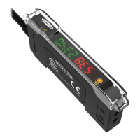
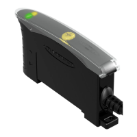
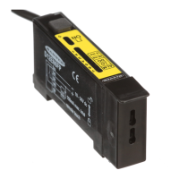
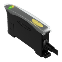
Dual Display Fiber Amplifier
Phone: 800.894.0412 - Fax: 888.723.4773 - Web: www.clrwtr.com - Email: info@clrwtr.com

 Loading...


