For Sales and Support, Contact Walker EMD • Toll-free: (800) 876-4444 • Tel: (203) 426-7700 • Fax: (203) 426-7800 • www.walkeremd.com
Light SET
• Sets a threshold a programmable % offset below the presented condition
• Changes output state on any condition darker than the threshold condition
• Threshold can be adjusted using “+” and “-” rocker button (Manual Adjust)
• Recommended for applications where only one condition is known, for example a stable light background with varying darker targets
• See Program Mode on page 3 for programming the Offset Percent setting
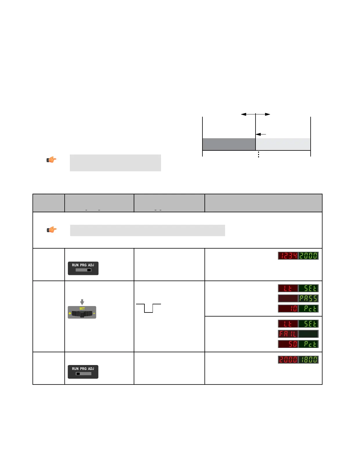
A single sensing condition is presented, and the sensor positions a threshold a programmable % offset below the presented condition. When a condition darker than the
threshold is sensed, the output either turns ON or OFF, depending on the LO/DO switch setting (see LO/DO Switch in Top Panel Interface on page 2).
Light SET and Manual Adjust
• Moves switching threshold value up or down to make adjustments
• Slide Mode switch to ADJ to enter Adjust mode
• Press “+” to increase; press “-” to decrease
• GREEN display shows the switching threshold value
• 2 seconds after adjustment, the GREEN display will flash 3 times to confirm
• Slide Mode switch to RUN to complete operation
Remember: Manual adjustments are disabled
when Auto Thresholds are ON
Threshold position
adjusted by
Manual Adjust
Sensor positions
threshold a programmable
% offset below the
presented condition
Darkest
(no signal)
Most Light
(saturated
signal)
Output OFF Output ON
Condition
Presented
Figure 5. Light SET (Light Operate shown)
SET Button
0.04 seconds < "Click" < 0.8 seconds
Remote Input
0.04 seconds < T < 0.8 seconds
Result
Note: TEACH Selection must be programmed to Lt SEt (see Program Mode on page 3 )
Enter Adjust
Mode
• Set Mode switch to ADJ
No action is required; sensor is ready
for Light SET method
Display: Red - Signal Level; Green -
Threshold
SET Sensing
Condition
• Present sensing condition
• Click the SET rocker button
• Present sensing condition
• Single-pulse the remote input
Threshold Condition Accepted
Displays read "Lt SEt" then alternate
"PASS" with % Offset*; Sensor returns
to Adjust mode
Threshold Condition Unacceptable
Displays read "Lt SEt" then alternate
FAIL with minimum % Offset* for sens-
ing condition; Sensor returns to Adjust
mode
Return to RUN
Mode
• Move Mode switch to RUN
No action required; sensor returns to
RUN mode automatically
Display: Red - Signal Level; Green -
Threshold
* Troubleshooting on page 10 for more explanation of the % Offset displayed after the Light SET method
DF-G1 - Expert Fiber Amplifier Install Sheet
P/N 161275 Rev. A www.bannerengineering.com - tel: 763-544-3164 7
 Loading...