For Sales and Support, Contact Walker EMD • Toll-free: (800) 876-4444 • Tel: (203) 426-7700 • Fax: (203) 426-7800 • www.walkeremd.com
Calibration SET
• Sets a threshold exactly at the presented condition
• Threshold can be adjusted using “+” and “-” rocker button (Manual Adjust)
A single sensing condition is presented, and the sensor positions a threshold exactly at the presented condition. When a condition lighter than the threshold is sensed, the
output either turns ON or OFF, depending on the LO/DO switch setting (see LO/DO Switch in Top Panel Interface on page 2).
Calibration SET and Manual Adjust
• Moves switching threshold value up or down to make adjustments
• Slide Mode switch to ADJ to enter Adjust mode
• Press “+” to increase; press “-” to decrease
• GREEN display shows the switching threshold value
• 2 seconds after adjustment, the GREEN display will flash 3 times to confirm
• Slide Mode switch to RUN to complete operation
Remember: Auto Thresholding is automatically
disabled in Calibration SET
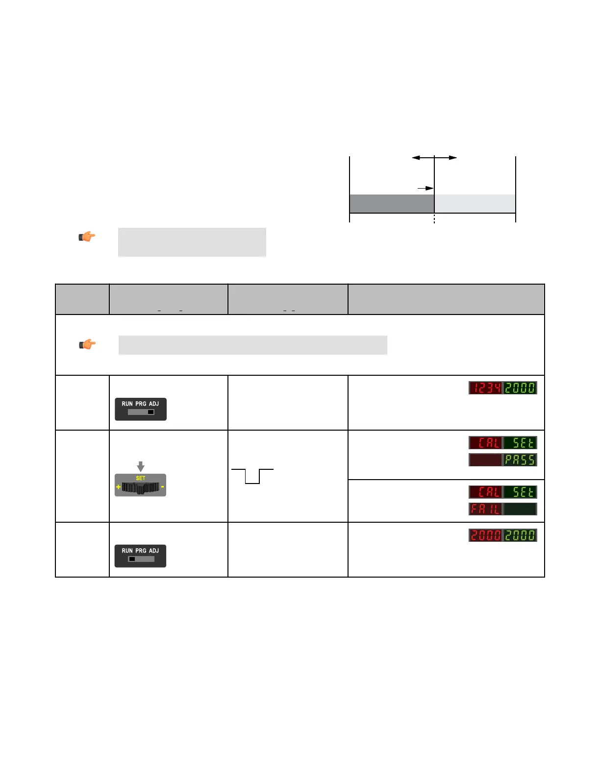
Sensor positions
threshold exactly at
the presented condition
Threshold position
adjusted by
Manual Adjust
Darkest
(no signal)
Most Light
(saturated
signal)
Output OFF Output ON
Condition
Presented
Figure 7. Calibration SET (Light Operate shown)
SET Button
0.04 seconds < "Click" < 0.8 seconds
Remote Input
0.04 seconds < T < 0.8 seconds
Result
Note: TEACH Selection must be programmed to CAL SEt (see Program Mode on page 3 )
Enter Adjust
Mode
• Set Mode switch to ADJ
No action required; sensor is ready for
Calibration SET method
Display: Red - Signal Level; Green -
Threshold
SET Sensing
Condition
• Present sensing condition
• Click the SET rocker button
• Present sensing condition
• Single-pulse the remote input
Threshold Condition Accepted
Displays read "cAL SEt" then flashes
"PASS"; Sensor returns to Adjust
mode
Threshold Condition Unacceptable
Displays read "cAL SEt" then flashes
"FAIL"; Sensor returns to Adjust mode
Return to RUN
Mode
• Move Mode switch to RUN
No action required; sensor returns to
RUN mode automatically
Display: Red - Signal Level; Green -
Threshold
DF-G1 - Expert Fiber Amplifier Install Sheet
P/N 161275 Rev. A www.bannerengineering.com - tel: 763-544-3164 9
 Loading...