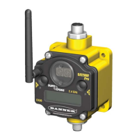
1. Industrial ethernet port, female.
2. Housing. The rugged, industrial DX80 housing meets IEC IP67
standards.
3. Mounting hold, #10/M5 clearance. Mounting Holes accept metric
M5 or UNC/UNF #10 hardware -- DIN rail mount adapter bracket
available.
4. 5-Pin M12 Euro-style quick-disconnect serial port
2.5 Wiring Diagrams
Use the following drawings to correctly wire power and I/O to the SureCross Wireless radio devices. For more information
about wiring sensors to the SureCross devices, refer to Sensor Connections.
2.5.1 5-pin Euro-Style Wiring for Gateways
Wiring the 5-pin Euro-style connector depends on the model and power requirements of the device. Connecting dc power
to the communication pins will cause permanent damage.
Wire No.
Wire Color Description
1 Brown 10–30V dc
2 White RS485 / D1 / B / +
3 Blue dc common (GND)
4 Black RS485 / D0 / A / –
5 Gray Comms Gnd
2.5.2 5-pin Euro-Style Wiring for Nodes
Wiring the 5-pin Euro-style connector depends on the model and power requirements of the device. For FlexPower devices,
do not apply more than 5.5V to the gray wire.
Wire No.
Wire Color 10–30V dc Powered Battery Powered
1 Brown 10–30V dc
2 White
3 Blue dc common (GND) dc common (GND)
4 Black
5 Gray 3.6–5.5V dc
SureCross DX80 and Performance DX80 Product Manual
10 www.bannerengineering.com - tel: 763-544-3164 Rev. J
 Loading...
