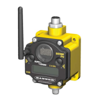
Valid Network IDs are 01 through 32, in decimal, established using both rotary dials. The left dial may be set to 0, 1, 2,
or 3. The right dial may be set from 0 to 9 when the left dial is at 0, 1, or 2; or set to 0 through 2 when the left dial is
at 3. (Positions A through F are invalid network ID numbers.)
When installing special kits with pre-mapped I/O, indicated by device model numbers beginning in DX80K, return the rota-
ry dials to their original positions after binding. If the rotary dials are not returned to their original positions, the I/O map-
ping will not work.
3.5 LED Behavior for the Gateways
After powering up and binding the Gateway and its Nodes, verify all devices are communicating properly. When testing
communication between the Gateway and Node, all radios and antennas should be at least two meters apart or the com-
munications may fail.
LED 1
LED 2 Gateway Status
(solid green)
Power ON
(flashing red) (flashing red)
Device Error
(flashing yellow)
Modbus Communication Active
(flashing red)
Modbus Communication Error
For Gateway and Ethernet Bridge systems, active Modbus communication refers to the communication between the Gate-
way and the Ethernet Bridge. For GatewayPro systems, the Modbus communication LEDs refer to the communication inter-
nal to the GatewayPro. For Gateway only systems, the Modbus communication LEDs refer to the communication between
the Gateway and its host system (if applicable).
3.6 LED Behavior for the Nodes
After powering up and binding the Gateway and its Nodes, verify all devices are communicating properly. A Node will not
sample its inputs until it is communicating with its Gateway. When testing communication between the Gateway and Node,
all radios and antennas should be at least two meters apart or the communications may fail.
LED 1
LED 2 Node Status
(flashing green)
Radio Link Ok
(flashing red) (flashing red)
Device Error
(flashing red, 1 per 3 sec)
No Radio Link
3.7 Conducting a Site Survey (Gateway and Nodes)
A Site Survey, also known as a Radio Signal Strength Indication (RSSI), analyzes the radio communications link between the Gateway
and any Node within the network by analyzing the radio signal strength of received data packets and reporting the number of missed
packets that required a retry.
Perform a Site Survey before permanently installing the radio network to ensure reliable communication. Activate Site Sur-
vey mode from either the Gateway buttons or the Gateway Modbus holding register 15. Only the Gateway can initiate a
Site Survey, and the Site Survey analyzes the radio communications link with one Node at a time.
3.7.1 Conducting a Site Survey Using the Menu System
Initiate a Site Survey using the Gateway’s buttons and menu system.
1. Remove the rotary dial access cover.
2. To check the status of Node 1, change the Gateway’s right rotary dial to 1.
The Gateway is now enabled to read the status of Node 1; the display scrolls through the Node’s I/O status.
SureCross DX80 and Performance DX80 Product Manual
Rev. J www.bannerengineering.com - tel: 763-544-3164 17

 Loading...