6.7 Hydraulic circulation system (Main circuit)
The hydraulic system sketch sees Fig. 6.10.
The hydraulic circulation system of the main circuit is complicated with the
hydraulic for power steering. The hydraulic piping is of O-ring fitting type with excellent
sealing performance, providing secure oil tightness.
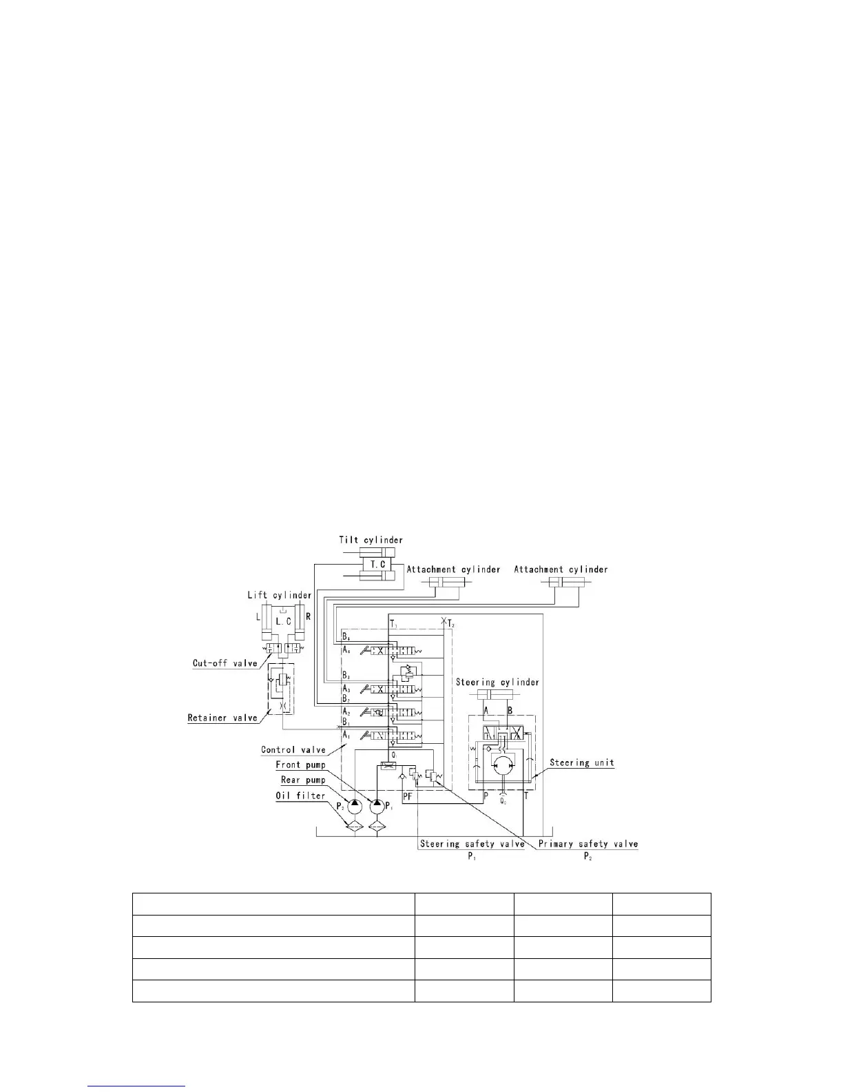
The hydraulic oil sent from the rear main pump flows directly to the control valve,
while the hydraulic oil sent from the front main pump is divided by the flow divider valve
in two portions for steering and load handling operation.
The hydraulic oil for load handling flows into the control valve and mingles with the
hydraulic oil from the rear main pump. With the control valve in neutral position, the oil
returns to the oil tank, passing through the valve.
When the lift lever is pulled, the hydraulic oil from the control valve flows through
the flow regulator valve and reaches the lower part of the lift cylinder piston to push up
the piston rod. When the lift lever is pushed, the circuit between the lower part of the lift
cylinder piston and the oil tank is opened, and the piston begins to descend due to the
weight of the piston rod, lift bracket, forks, etc. In this case, the oil returning to the
control valve is regulated by the flow regulator.
When the tilt lever is operated, the hydraulic oil from the main pump reaches one
side of the piston to push it. The oil pushed by the piston returns to the oil tank through
the control valve.
Fig.6.10 Hydraulic system