POLARIS BASIC - for Zone 1/21
POLARIS Panel PCs 5.7" / 10.4" / 12.1"
Installation
Technical data subject to change.
06/2017
EN 27/45
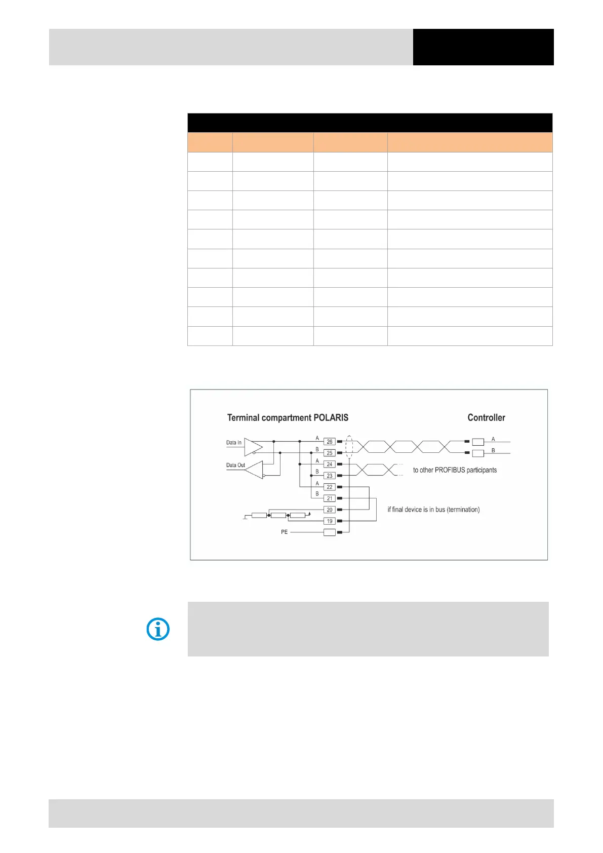
6.6.5 PROFIBUS-DP interface (optional)
Configuration PROFIBUS-DP (BARTEC)
Terminal Interface Signal Remarks
X17 not connected
X18 not connected
X19 Interface COM 1 Termination B2 Bridge for terminating network (B1-B2)
X20 Interface COM 1 Termination A2 Bridge for terminating network (A1-A2)
X21 Interface COM 1 Termination B1 Bridge for terminating network (B1-B2)
X22 Interface COM 1 Termination A1 Bridge for terminating network (A1-A2)
X23 Interface COM 1 Out B Signal B Output
X24 Interface COM 1 Out A Signal A Output
X25 Interface COM 1 In B Signal B Input
X26 Interface COM 1 In A Signal A Input
Connection of a controller via the PROFIBUS-DP interface of the POLARIS.
Maximum line length: see PNO specification.
Pins 26-24-22, 25-23-21 are already connected inside.
See the interface description from the controller manufacturer for the relevant pin
assignment of the controller.