Installation
POLARIS BASIC - for Zone 1/21
POLARIS Panel PCs 5.7" / 10.4" / 12.1"
EN 34/45
Technical data subject to change.
06/2017
6.8.6 Examples of shielding connections
ATTENTION
Device can be damaged by differences in potential!
Avoid differences in potential.
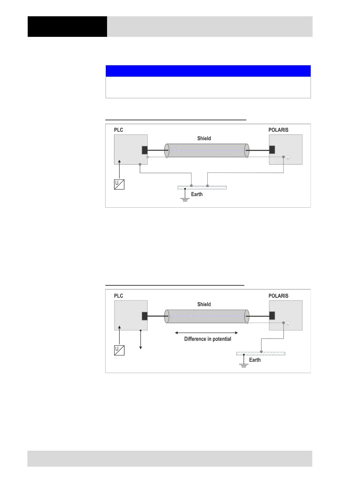
Double-sided shield connection on the connecting cables
Illustration 12: Example of double-sided shield connection
Generally, connection of the shielding at both ends results in optimum damping of all
interference frequencies. This method is to be recommended when there is good
equipotential bonding between the individual units. In such cases it is possible to make
use of the controller’s voltage supply cable even if this is not electrically isolated.
Single-sided shield connection on the connecting cables
Illustration 13: Example of single-sided shield connection
Connection of the shielding at one end only is recommended when there is inadequate
equipotential bonding, or none at all. In such cases an electrically isolated power supply
unit must be used. Before the equipment goes into service the directions from the
controller manufacturer regarding proper assembly and operation must be read carefully.
They should then be applied taking full account of the recommendations we make here.