12 Assembly and operating instructions / EN
5. Functional description
After switch-on, the RLA
net
carries out a self-test. All values on
the display as well as all LEDs are shown for a period of 1
second. The alarm relay is energised until the self-test is
completed. The RLA
net
then switches to operating mode and the
alarm relay drops out. The leakage monitoring of the system is
now active. Visibly on: red “power” LED.
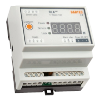
There are 3 LEDs on the front of the RLA
net
indicating operational
and sensor status (leakage detected and open circuit) and 2
LEDs on the board for Modbus RTU communication
(RX=incoming and TX=outgoing).
After detecting a leak, the RLA
net
generates a message that
specifies the location to the meter, and the alarm relay picks up.
The relay contacts can be used for a local or "remote" alarm,
control valve or other devices.
During the leak notification, the beeper can be switched off with
the "confirm" button. The leak message itself remains on the
display. The alarm relay remains energised.
The beeper can also be switched off in the service programme by
pressing the "confirm leak" soft button.
In this case, the RLA
net
is also reset for 0.5 seconds, the alarm
relay drops out, the LEDs and the display go to "normal" (no
leak).
If the leakage is still present, the message appears as described.
If the sensor cable breaks, the RLA
net
generates a corresponding
message on the display. The alarm relay remains de-energised.
6. System planning
The installation must be carried out carefully in compliance with
all legal requirements and in compliance with the technical data of
all components used.
For system planning, please also note Chapter 16.3 "Example
system planning" and 16.6 "Information on project planning,
wiring diagrams".
Please note for point sensors PSO and PSO+:
– Consider the voltage drop in the supply line
– Comply with the current limit of the voltage source
6.1. Modbus RTU communication
The RLA
net
has a digital interface for forwarding the leakage
system states, for example to a building control centre. Up to 250
pieces of RLA
net
can be addressed in a Modbus RTU network via
this interface. For connection to the building control centre,
please see the wiring diagram in Chapter 3.1.
Only the service software is suitable for parameterising the
leakage system. Direct access to system parameters via the
Modbus RTU protocol is not possible.
The Modbus communication parameters are described in the
supplementary documentation "RLAnet Modbus Communication
Protocol". This is available at www.bartec.com. Keyword search
for “RLA”.
 Loading...