11-85G5-7D0002/B-EHT-10/2021 13
7. Assembly
The assembly must be carried out carefully and in accordance
with system planning, the applicable national standards,
regulations and approvals, the technical data of the individual
components and these assembly and operating instructions.
7.1. Mechanical assembly
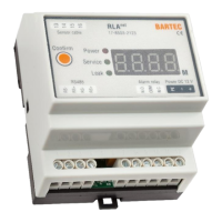
The RLA
net
can be easily attached to a TS35 top-hat rail using a
top-hat rail clip.
The RLA
net
may only be installed and operated within an
approved electrical control cabinet. Please ensure adequate
ventilation during operation, if necessary provide air supply and
exhaust ducts in the control cabinet. The RLA
net
must not be
exposed to direct sunlight or moisture.
BARTEC recommends checking the electrodes of the PS sensors
and the optics of the PSO sensors to ensure they are clean and
free of grease. Clean the electrodes and the optics with alcohol or
a degreasing household cleaner.
The plug-in connections of the sensors and the sensor cable
required for the installation must be routed so that they are
protected against moisture. When monitoring surfaces, spacers
available as accessories must be inserted between the plug
connection and the floor.
7.2. Electrical assembly
The RLA
net
monitoring device must be connected according to the
wiring diagram (see technical data). Before connection, the ends
of multi-core or fine-stranded conductors must be stripped and
fitted with ferrules.
The protective earth conductor must be connected to the
grounding system of the power supply. Tests must be performed
to ensure continuity of grounding.
The strain relief of all cables must be ensured
7.3. Laying of the sensor cable
Example of laying under raised floors:
The sensor line must lie on the surface to be monitored. If
necessary, fix the sensor cable with suitable adhesive tape. The
surface to be glued onto must be dry, clean and largely free of
dust. Fasten the sensor cable at 1m intervals with BARTEC
fastening tape.
Do not fix the sensor cable directly to metal parts. This can falsify
the measurement results of the RLA
net
. Use non-detecting
connection lines, protective hoses or flexible hoses for wall ducts
or limiting constructions (line routes, etc.). The sensor cable can
be routed around boundary structures (cable routes). Ensure that
the sensor cable is adequately fastened and that the sensor cable
lies on the surface to be monitored.
Distillate from pipes and cooling units must not wet the sensor
line.
Structural damages to the sensor cable should be avoided as far
as possible. If structural avoidance is not possible, the label
"sensitive sensor cable" can be used. See Chapter 14 "System
accessories".
7.4. Connecting the point sensors
The conductive PS point sensors and the optical PSO+ point
sensors can be integrated into the wiring of the SCR sensor
cable.
The information in the operating instructions for the point sensors
on installation, commissioning, operation and maintenance must
be observed.

 Loading...