9440300990 14-3
DECS-250 Event Recorder
• Cross-current compensation enabled or disabled
• Grid Code enabled or disabled
• APC enabled or disabled
• LFSM enabled or disabled
• LVRT mode enabled or disabled
• Test mode enabled or disabled
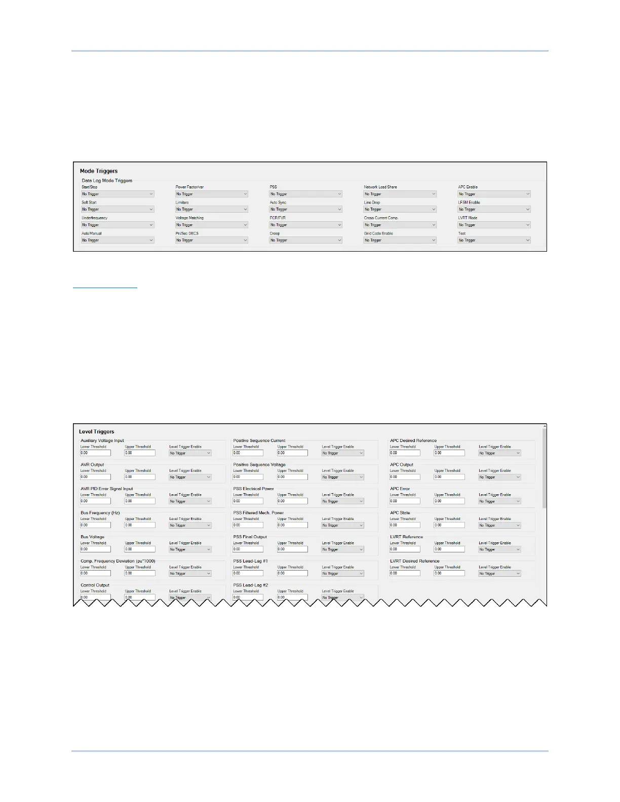
Mode trigger settings are illustrated in Figure 14-3.
Figure 14-3. Data Log Mode Triggers
Level Triggers
Level triggering initiates a data log based on the value of an internal variable. The variable can be a
minimum or maximum value and can be specified to trigger a record when the monitored variable crosses
a minimum threshold from above, or a maximum threshold from below. A minimum and maximum
threshold may also be selected for the monitored variable, causing the monitored value to trigger a record
when it rises above its maximum threshold or decreases below its minimum threshold.
Level triggers are configured in BESTCOMSPlus on the Level Triggers tab (Figure 14-4) in the Data Log
area of the Report Configuration. The Level Triggers tab consists of a list of parameters that can be
selected to trigger a data log. Each parameter has a level trigger enable setting which configures
triggering of a data log when the parameter increases above the upper threshold setting or decreases
below the lower threshold setting. The parameters available to trigger a data log are listed below.
Figure 14-4. Data Log Level Triggers
• APC desired reference
• APC error
• APC output
• APC state
• Auxiliary voltage input
• AVR output
• AVR PID error signal input
• Bus frequency
• Bus voltage
• Comp. frequency deviation
• Control output
• Cross current input
• Droop
• FCR error
• FCR output
• FCR state
• Field current
• Field voltage
• Frequency response
• FVR error