9440300990 21-15
DECS-250 BESTlogic™Plus
Name Description Symbol
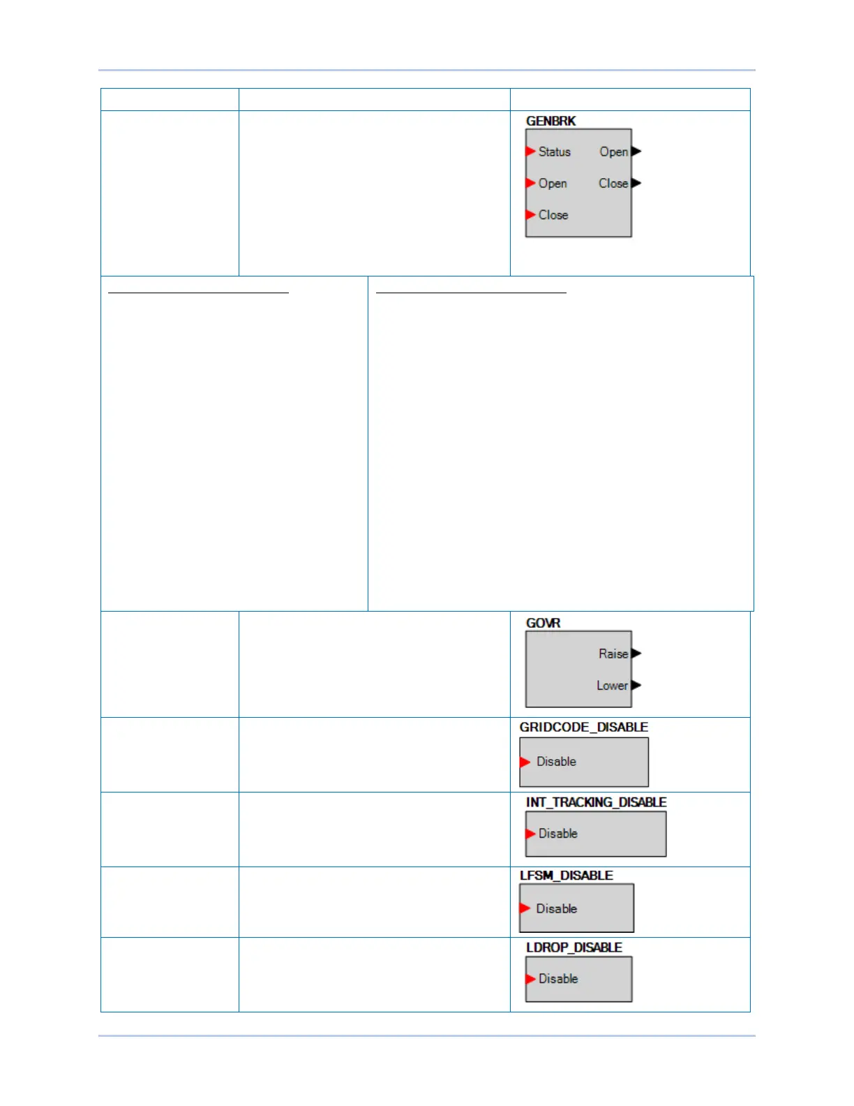
GENERATOR
BREAKER
This element is used to connect the breaker
open and close output signals from the
DECS-250 to physical output contacts to
open and close the generator breaker, and
map breaker status feedback to a contact
input. In addition, contact inputs can be
mapped to allow switches to be implemented
to manually initiate breaker open and close
requests. (Available when the controller is
equipped with the optional Auto synchronizer,
style number xxxxAxx)
GENERATOR BREAKER Inputs
Status: This input allows a contact input to be
mapped that will provide breaker status
feedback to the DECS-250. When the
contact input is closed, the breaker is
indicated to be closed. When the contact
input is open, the breaker is indicated to be
open.
Open: This input allows a contact input to be
mapped that can be used to initiate a manual
breaker open request. When this input is
pulsed closed, the breaker opens.
Close: This input allows a contact input to be
mapped that can be used to initiate a manual
breaker close request. When this input is
pulsed and the generator is stable, a close
request is initiated. If the Dead Bus Close
Enable parameter is TRUE, and the bus is
dead, the breaker will close. If the bus is
stable, the DECS-250 will synchronize the
generator to the bus, and then close the
breaker.
GENERATOR BREAKER Outputs
The outputs must be mapped to the contact outputs of the DECS-
250 that will be used to drive the breaker.
Open: This output is pulsed TRUE (closes the output contact it is
mapped to) when the DECS-250 is providing a signal to the
breaker to open. It will be a pulse if the Breaker Output Contact
Type is set to Pulse on the Breaker Hardware screen under
Synchronizer/Voltage Matching in the Settings Explorer, and the
length is determined by the Open Pulse Time. It will be a constant
output if the Generator Breaker Hardware Contact Type is set to
continuous. Note the pulse time must be set long enough for the
breaker to actually open before the pulse is removed.
Close: This output is pulsed TRUE (closes the output contact it is
mapped to) when the DECS-250 is providing a signal to the
breaker to close. It will be a pulse if the Breaker Output Contact
Type is set to Pulse on the Breaker Hardware screen under
Synchronizer/Voltage Matching in the Settings Explorer, and the
length is determined by the Open Pulse Time. It will be a constant
output if the Generator Breaker Hardware Contact Type is set to
continuous. Note the pulse time must be set long enough for the
breaker to actually open before the pulse is removed.
GOVERNOR Can be connected to inputs of other logic
blocks. When the Governor is being raised,
the Raise output is true. When being lowered,
the Lower output is true. (Available when the
controller is equipped with the optional Auto
synchronizer, style number xxxxAxx)
GRID CODE
DISABLE
When true, overall Grid Code functionality is
disabled.
INTERNAL
TRACKING DISABLE
When true, this element disables internal
tracking.
LFSM DISABLE When true, Grid Code LFSM is disabled.
LINE DROP
DISABLE
When true, this element disables line drop
when the unit is operating in AVR mode.