21-28 9440300990
BESTlogic™Plus DECS-250
check which views you would like to print. Next, the Print dialog box opens with the typical Windows
choice to setup the properties of printer. Execute this command, as necessary, and then select Print.
A Page Setup icon is also provided on the BESTlogicPlus Programmable Logic toolbar allowing you to
select Paper Size, Paper Source, Orientation, and Margins.
Clearing the On-Screen Logic Diagram
Click on the Clear button to clear the on-screen logic diagram and start over.
BESTlogic™Plus Examples
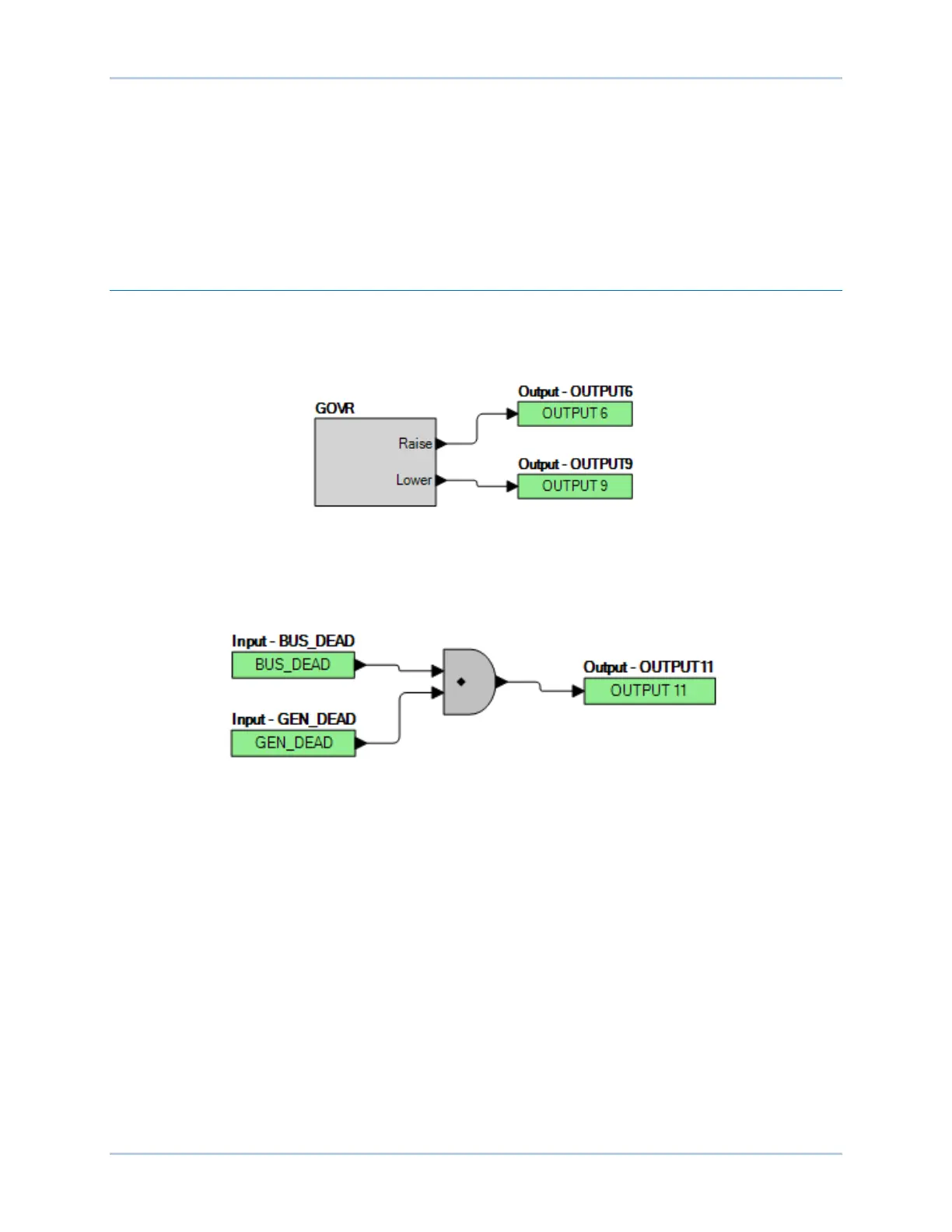
Example 1 - GOVR Logic Block Connections
Figure 21-12 illustrates the GOVR logic block and two output logic blocks. Output 6 is active while the
governor is being raised and Output 9 is active while the governor is being lowered.
Figure 21-12. Example 1 - GOVR Logic Block Connections
Example 2 - AND Gate Connections
Figure 21-13 illustrates a typical AND gate connection. In this example, Output 11 will become active
when the bus and the generator are dead.
Figure 21-13. Example 2 - AND Gate Connections