EasyManuals Logo

Basler DECS-250 User Manual

Basler DECS-250
374 pages
To Next Page IconTo Next Page
To Previous Page IconTo Previous Page
Page #348 background imageLoading...
Page #348 background image
32-6 9440300990
Analog Expansion Module DECS-250
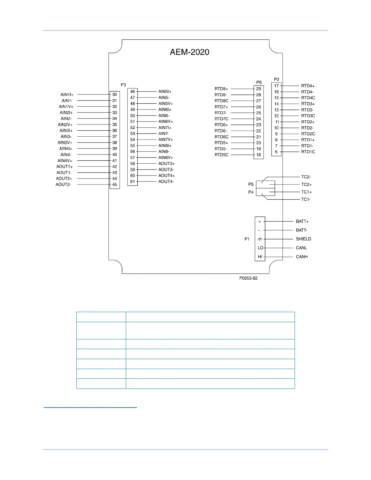
Figure 32-2. Input and Output Terminals
Table 32-2. Input and Output Terminals
Connector
Description
P1
Operating Power and CAN bus
P2
RTD Inputs 1 - 4
P3
Analog Inputs 1 - 8 and Analog Outputs 1 - 4
P4
Thermocouple 1 Input
P5
Thermocouple 2 Input
P6
RTD Inputs 5 - 8
External Analog Input Connections
Voltage input connections are shown in Figure 32-3 and current input connections are shown in Figures
36 through 38. When using the current input, AIN V+ and AIN I+ must be tied together.

Questions and Answers:

Question and Answer IconNeed help?

Do you have a question about the Basler DECS-250 and is the answer not in the manual?

Basler DECS-250 Specifications

General IconGeneral
BrandBasler
ModelDECS-250
CategoryControl Systems
LanguageEnglish

Related product manuals