9440300990 32-9
DECS-250 Analog Expansion Module
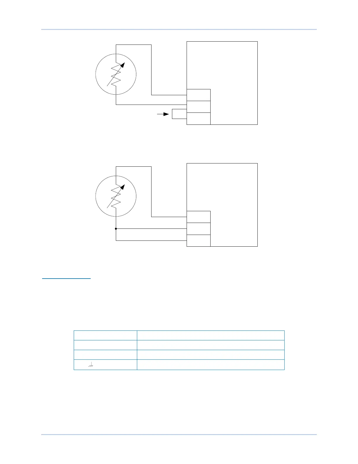
Figure 32-7. External Two-Wire RTD Input Connections
Figure 32-8. External Three-Wire RTD Input Connections
CAN Bus Interface
These terminals provide communication using the SAE J1939 protocol and provide high-speed
communication between the Analog Expansion Module and the DECS-250. Connections between the
AEM-2020 and DECS-250 should be made with twisted-pair, shielded cable. CAN Bus interface terminals
are listed in Table 32-3. Refer to Figure 32-9 and Figure 32-10.
Table 32-3. CAN bus Interface Terminals
CAN high connection (yellow wire)
CAN low connection (green wire)
RTD
1+
RTD1–
RTD1C
AEM-2020
Jumper
P0053-64
BLACK
RED
RTD
1+
RTD1–
RTD1C
AEM-2020
P0053-65
RED
BLACK
BLACK