11-6 9440300990
Limiters DECS-250
UEL settings are illustrated in Figure 11-7 and Figure 11-8.
Underexcitation limiting is implemented through an internally-generated UEL curve or a user-defined UEL
curve. The internally-generated curve is based on the desired reactive power limit at zero real power with
respect to the generator voltage and current rating. The absorbed reactive power axis of the curve on the
UEL Custom Curve screen can be tailored for your application.
A user-defined curve can have a maximum of five points. This curve allows the user to match a specific
generator characteristic by specifying the coordinates of the intended leading reactive power (kvar) limit
at the appropriate real power (kW) level.
The levels entered for the user-defined curve are defined for operation at the rated generator voltage. The
user-defined UEL curve can be automatically adjusted based on generator operating voltage by using the
UEL voltage dependency real-power exponent. The user-defined UEL curve is automatically adjusted
based on the ratio of the generator operating voltage divided by the generator rated voltage raised to the
power of the UEL voltage dependency real-power exponent. UEL voltage dependency is further defined
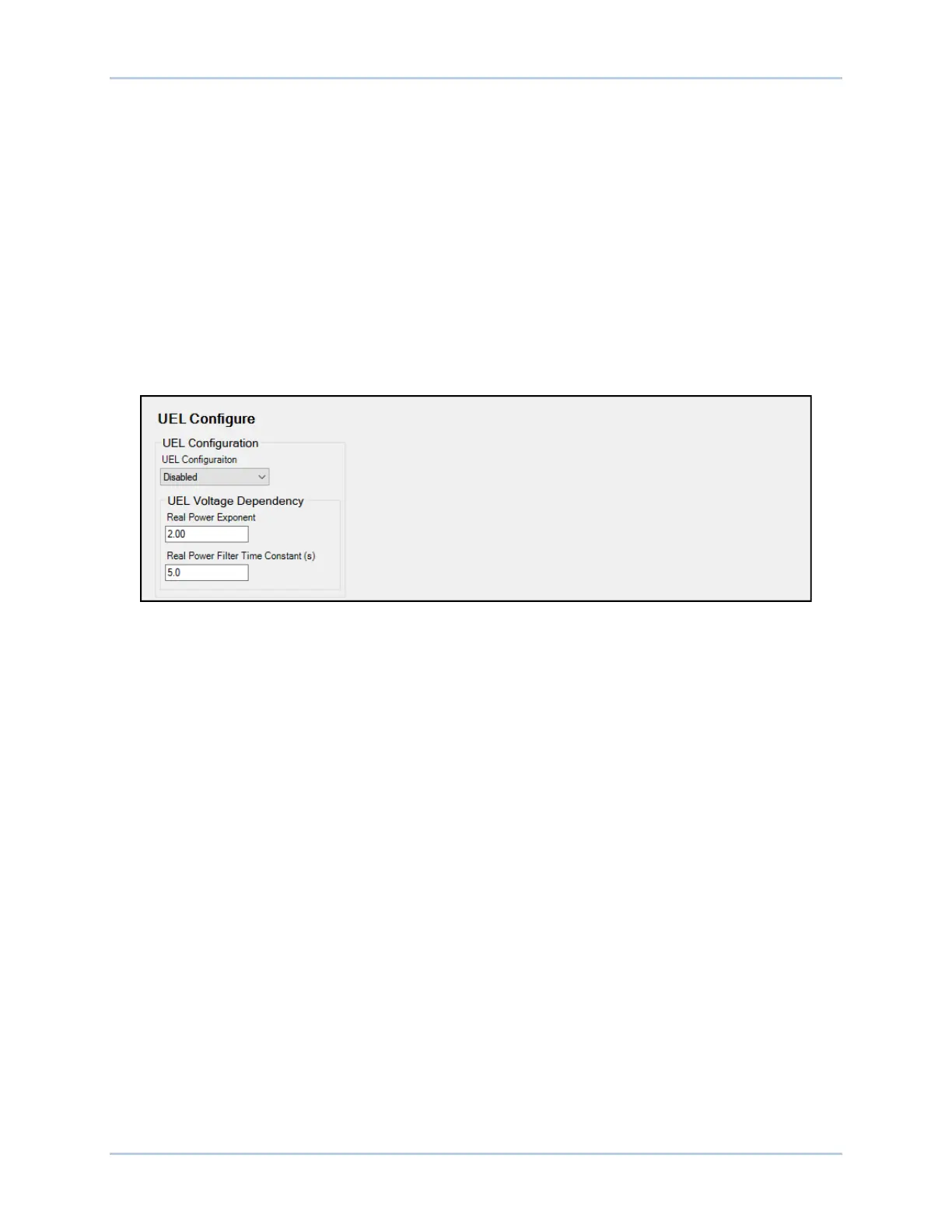
by a real power filter time constant that is applied to the low-pass filter for the real power output.
Figure 11-7. UEL Configuration Settings