12-8 9440300990
Grid Code DECS-250
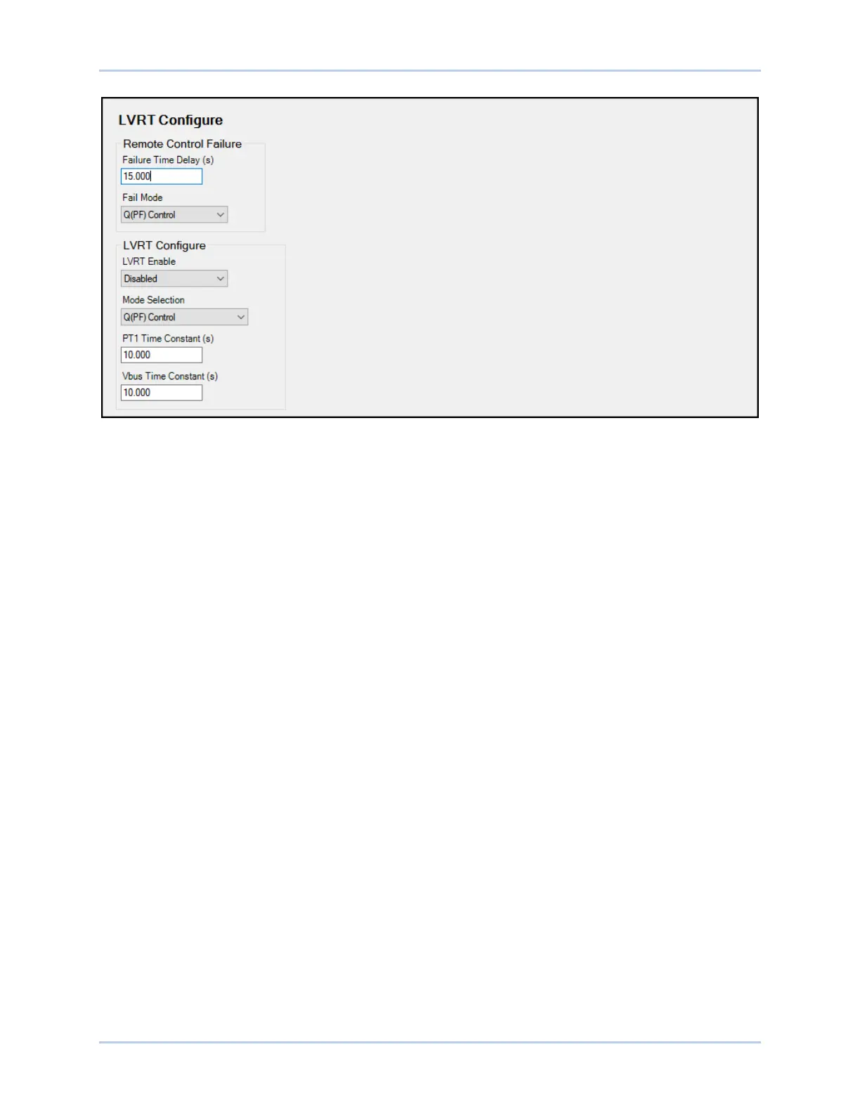
Figure 12-7. Reactive Power Control, LVRT Configure Screen
Reactive Power as a Function of Voltage - Q(U)
BESTCOMSPlus Navigation Path: Settings Explorer, Grid Code Settings, Reactive Power Control, Q(U)
HMI Navigation Path: Settings, Operating Settings, Grid Code Settings, Reactive Power Control, Q(U)
Settings
In this mode the reactive power output of the machine is adjusted as Grid Voltage fluctuates. The curve is
specified by a slope which goes through the point U = 1.00 along with a Maximum Reactive Power setting
and a Minimum Reactive Power settings both of which are in per unit.
The slope is derived from two points determined by the grid operator at the time of commissioning. The
first point is the reference voltage U
Q0, ref
/ U
C
, at which reactive power output is 0. The second point is (U
MAX / U
C
, Q MAX
under-excited
/ P b inst ). The slope of the characteristic m is calculated according to:
Slope m = (Q MAX
underexcited
/ P inst b) / (U MAX /U C - U
Q0, ref
/ U C)
Equation 12-1. Slope
The slope of the characteristic must be in a range of 5 to 16.5. Unless specified, the default values for
these parameters are:
(U MAX /U
C
, Q MAX
under-excited
/ P b inst ) = (1.04,0.33) and U
Q0, ref
/ U
C
= 1.00
Equation 12-2. Default Values for Slope Equation
The value for the Max Reactive Power setting is equal to Q MAX
under-excited
/ P b inst from the point (U
MAX / U c , Q MAX
under-excited
/ P b inst ). The value of the Min Reactive Power setting is equal to the
negative of the Max Reactive Power setting.
The voltage at the grid connection point may be averaged or filtered.
There is a voltage dead band adjustable from 0.00 to 0.05 per unit in increments of 0.001 per unit. The
default is zero. When the voltage goes outside the dead band, a new setpoint is calculated from the
characteristic itself or the intersection of the measured mains voltage and the exceeded dead band limit.
There is also an operating setpoint (U
Q0
/ U
C
) which is the operating voltage at which reactive power
output will be zero. The operating setpoint is typically a fixed value but may be remotely adjusted in steps
of 0.5% U
C
. Such adjustment results in a horizontal shift of the characteristic (see Figure 12-8). The ability
to remotely modify the setpoint is specified by the network operator at the time of system planning.