9440300990 12-9
DECS-250 Grid Code
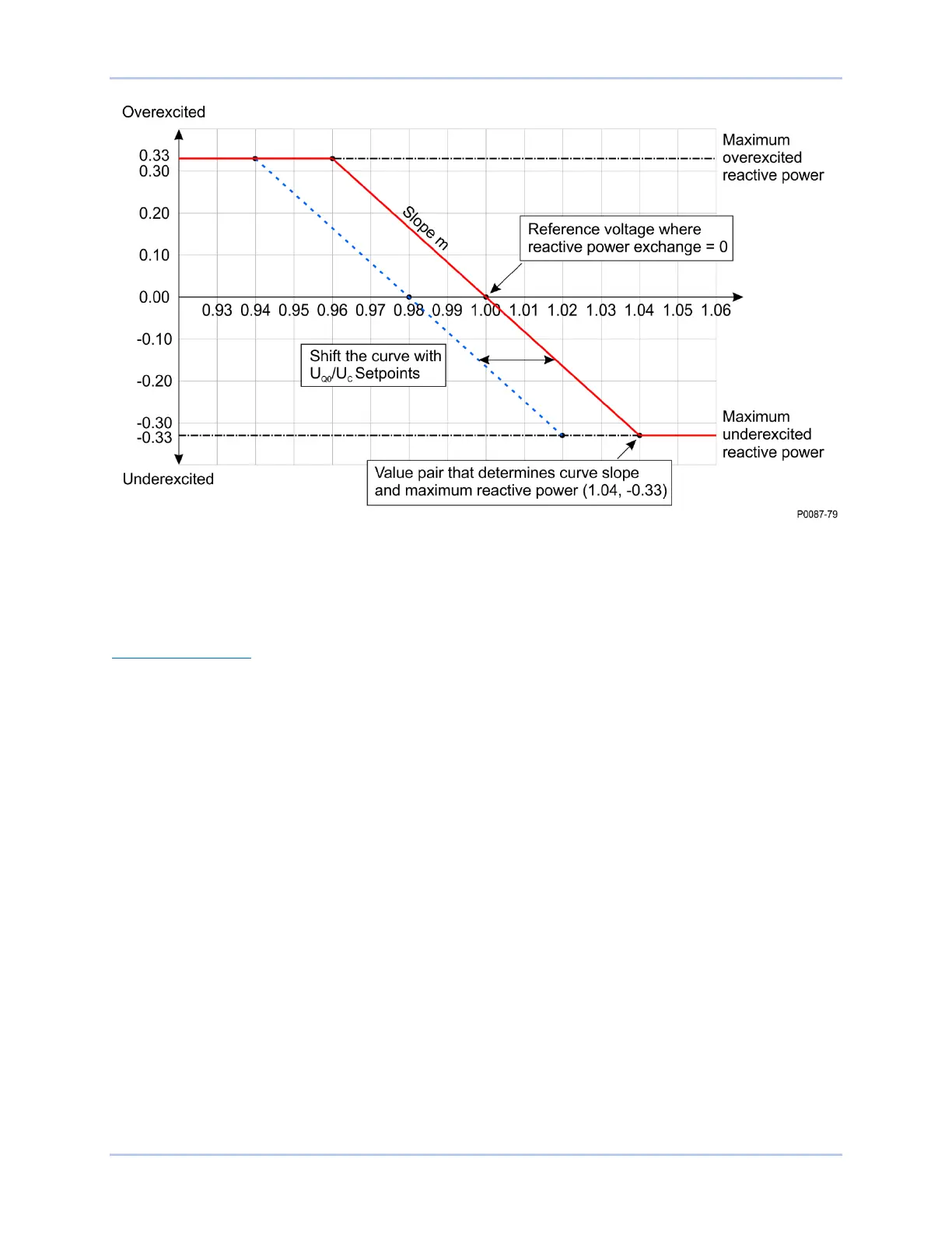
Figure 12-8. Reactive Power Q(U) Characteristic Curve
In the event of a remote communications failure while in Q(U) mode, the controller may continue
operating in Q(U) mode using the last valid value for U
Q0
/ U
C
received over communications, or switch to
Q(PF) operation with a PF of 1.0. The network operator may also arrange a switch to one of the other
Reactive Power control modes instead.
Adjustment Sources
The Q(U) setpoint may be adjusted by the DECS-250 auxiliary input, an Analog Expansion Module
AEM-2020 analog input, or via remote communication (Modbus
®
or CAN bus). For all adjustment
sources, the value of the Q(U) Gain setting is applied to the value read from the selected input. Refer to
the CAN Communication and Modbus Communication chapters for more information on adjusting the
setpoint via remote communication.
Auxiliary Input
To use the DECS-250 auxiliary input as the Q(U) adjustment source, make the following settings:
• On the Auxiliary Input screen, set the Input Function setting to Grid Code Input. Refer to the
Auxiliary Control chapter for details.
• On the Active Power Control screen, set the Adjust Source setting to Auxiliary Input.
Refer to the Auxiliary Control chapter for details on how the auxiliary voltage (Vaux) is calculated.
Vaux is multiplied by 0.01 and the value of the Q(U) Gain setting:
(APC Adjust = Vaux x 0.01 x Q(U) Gain).