12-10 9440300990
Grid Code DECS-250
Figure 12-9. Reactive Power Control, Q(U) Screen
Reactive Power as a Function of Active Power – Q(P)
BESTCOMSPlus Navigation Path: Settings Explorer, Grid Code Settings, Reactive Power Control, Q(P)
HMI Navigation Path: Settings, Operating Settings, Grid Code Settings, Reactive Power Control, Q(P)
Settings
In this mode the reactive power output of the machine is adjusted as the real power output fluctuates
(Q = f(P)).
A filter time constant setting is available for the measured power level. The characteristic curve is
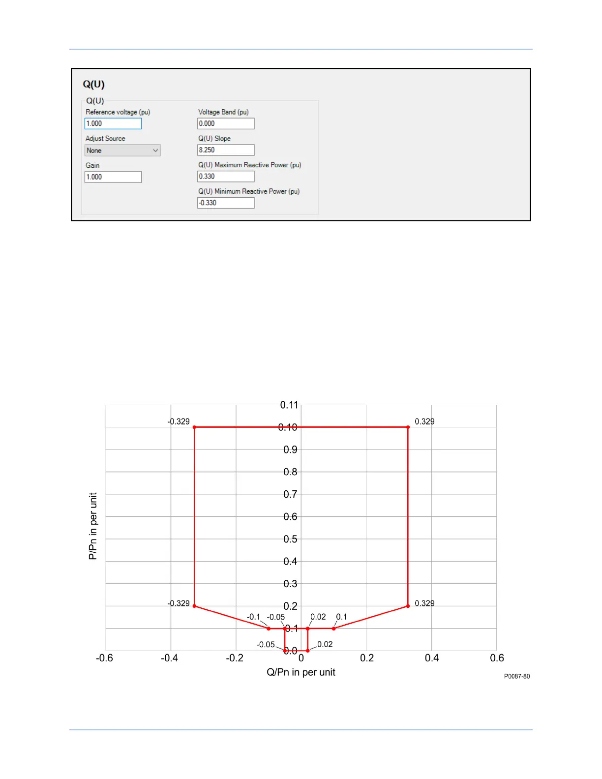
specified by up to 10 points relating desired Q output to exported power. Perform linear interpolation
between the points. The active power coordinate for each point may range from 10% to 100% active
power and the range for the reactive power level must conform to Figure 12-10, below. Above 20% active
power, the reactive power range should be -0.33 to 0.33 per unit reactive power.
Figure 12-10. Q(P) Characteristic Curve
Figure 12-11 illustrates an example characteristic with five plotted points.