9440300990 12-11
DECS-250 Grid Code
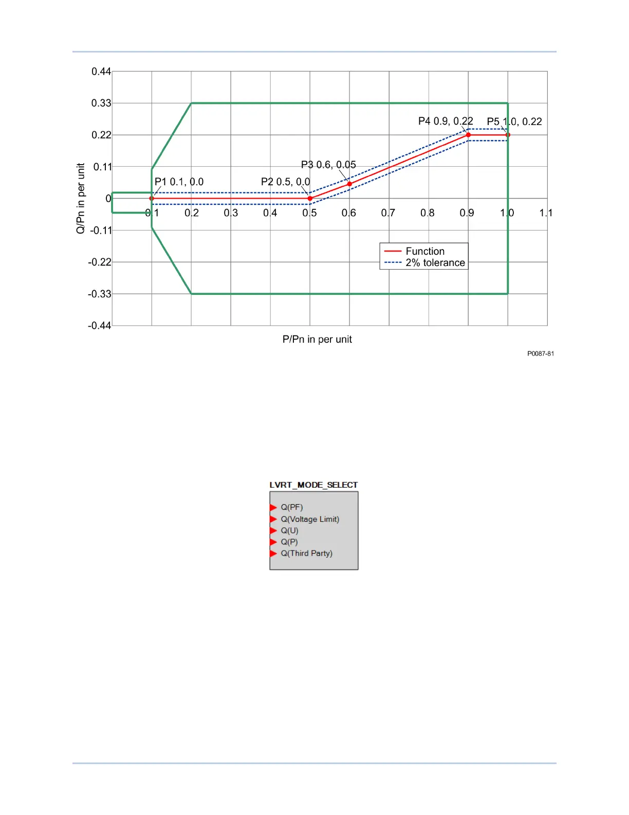
Figure 12-11. Q(P) Characteristic Curve Example
The network operator defines the characteristic curve during network planning. Remote setpoint
adjustment is not provided. However, it is possible to switch from this mode to another reactive power
control mode at any time through logic. Logic can also be set to switch reactive power control modes
upon a remote communications failure. Figure 12-12 illustrates the LVRT Mode Select logic element. See
the BESTlogicPlus chapter for details.
Figure 12-12. LVRT Mode Select Logic Element
If LVRT Mode is enabled, but no operating mode is specified, the default operating mode will be Power
Factor with a power factor setting of 1.0.