4
Sensor Wiring
1. When connecting to a microprocessed control box, the motion output and presence output wires may be connected to separate inputs or may
also be connected to a mutual input. Some controls may only have an activation input, while others may have an activation input, as well as a
safety (or presence) input.
Wiring the Wizard to an Automatic Door Control with Separate Activation and Safety Inputs
O
P
T
I
O
N
1
Color Microprocessed Controls
Red 12 to 24 VAC / VDC: -5% to +10%
Black 12 to 24 VAC / VDC: -5% to +10%
White Common at Door Control
Green Activation Input at Door Control
Brown Common at Door Control
Blue Safety Input at Door Control
Wiring the Wizard to an Automatic Door Control with Activation and Safety Wired to One Input
O
P
T
I
O
N
2
Color Controls Without Safety Circuit
Red 12 to 24 VAC / VDC: -5% to +10%
Black 12 to 24 VAC / VDC: -5% to +10%
White Common at Door Control
Green Activation Input at Door Control
Brown Common at Door Control
Blue Activation Input at Door Control
Wiring the Wizard to an Automatic Door Control with Activation and Safety Signal through Relay Only
O
P
T
I
O
N
3
Color Controls Without Safety Circuit
Red 12 to 24 VAC / VDC: -5% to +10%
Black 12 to 24 VAC / VDC: -5% to +10%
White Common at Door Control
Green Activation Input at Door Control
Brown Not Used
Blue Not Used
5 Installation (Continued)
2
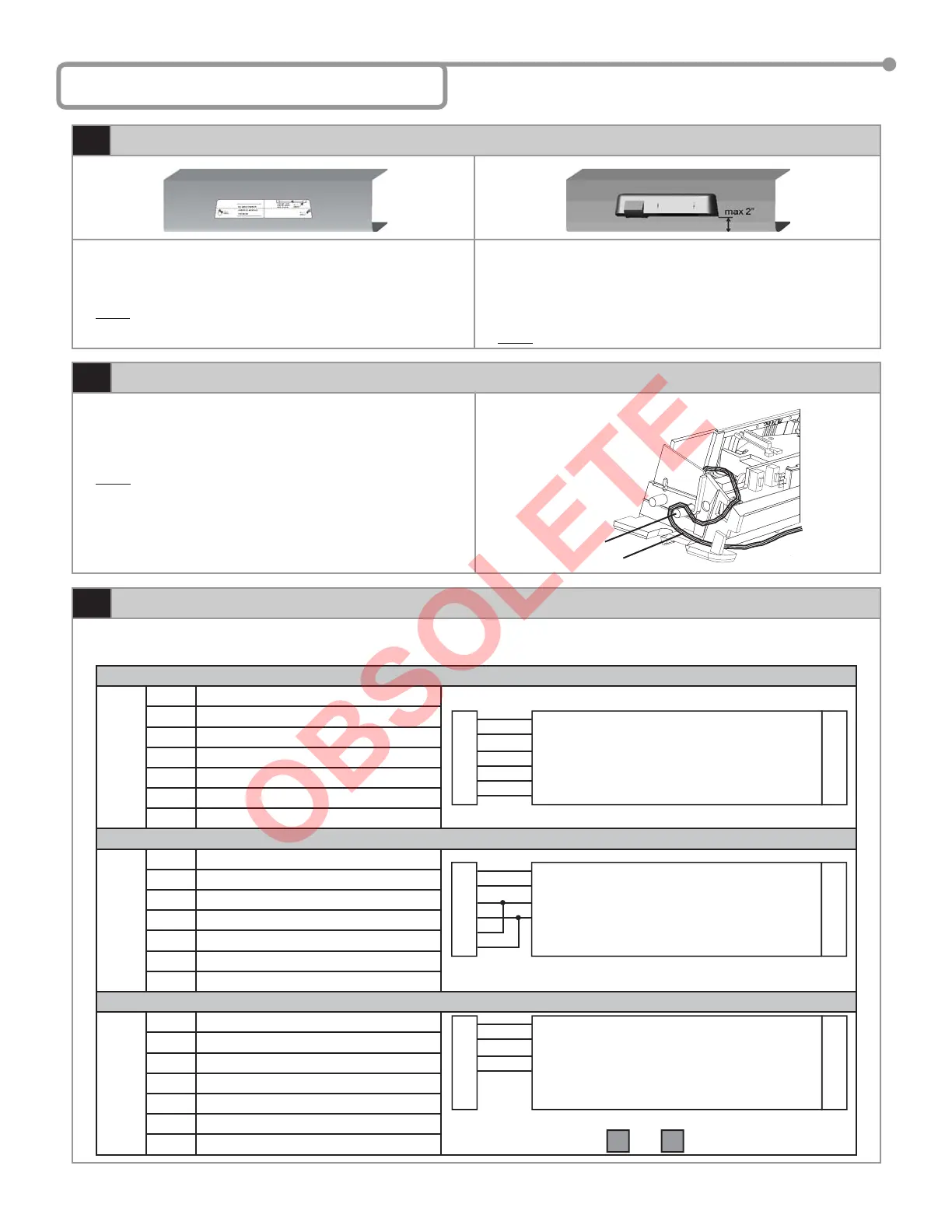
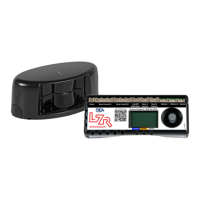
Mount Sensor
1. Attach mounting template to center of door header as shown
above. Template should be 0” to 2” above bottom edge of header.
Drill hole marked for wire passage and drill pilot holes for screw
mounting.
NOTE: Flush mount with bottom of header is necessary for all
negative IR angles.
2. Mount the sensor at a maximum height of 2” from the bottom line of
the door operator.
3. Insert mounting screws approximately halfway in and install the
Wizard on the screws. When in place, tighten screws to secure to
header.
NOTE: Leave cover off until mechanical adjustments are complete.
3
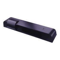
Cable Routing
1. With Wizard in place, locate the enclosed cable and feed the
stripped end through the wire passage hole in the header.
2. Leave enough slack to allow connection to the Wizard and proper
routing of wire around the plastic post.
NOTE: Observe proper routing of the cable as shown. This is to
divert rainwater from the Wizard if water should run down
the cable. Proper routing of the wire also provides easier
installation of the cover.
Plastic Post
Cable / Wire
75.5122.05 20070427 Page 3 of 13
W
I
Z
A
R
D
• PWR: Red - 12 to 24 VAC / VDC: -5% to +10%
• PWR: Black - 12 to 24 VAC / VDC: -5% to +10%
•
COM: White - Common at Door Control
• ACTIV: Green - Activation at Door Control
C
O
N
T
R
O
L
White and Green provide output for motion and presence detection
On Remote Control Set: To
F1 1
W
I
Z
A
R
D
• PWR: Red - 12 to 24 VAC / VDC: -5% to +10%
• PWR: Black - 12 to 24 VAC / VDC: -5% to +10%
• COM: White - Common at Door Control
• ACTIV: Green - Activation at Door Control
• COM: Brown - Connected to White Common
• SAFETY: Blue - Connected to Green Activation
C
O
N
T
R
O
L
Brown and Blue may be connected to White and Green
W
I
Z
A
R
D
• PWR: Red - 12 to 24 VAC / VDC: -5% to +10%
• PWR: Black - 12 to 24 VAC / VDC: -5% to +10%
•
COM: White - Common at Door Control
• ACTIV: Green - Activation at Door Control
• COM: Brown - Common at Door Control
• SAFETY: Blue - Safety at Door Control
C
O
N
T
R
O
L