6 Mechanical Adjustments
1
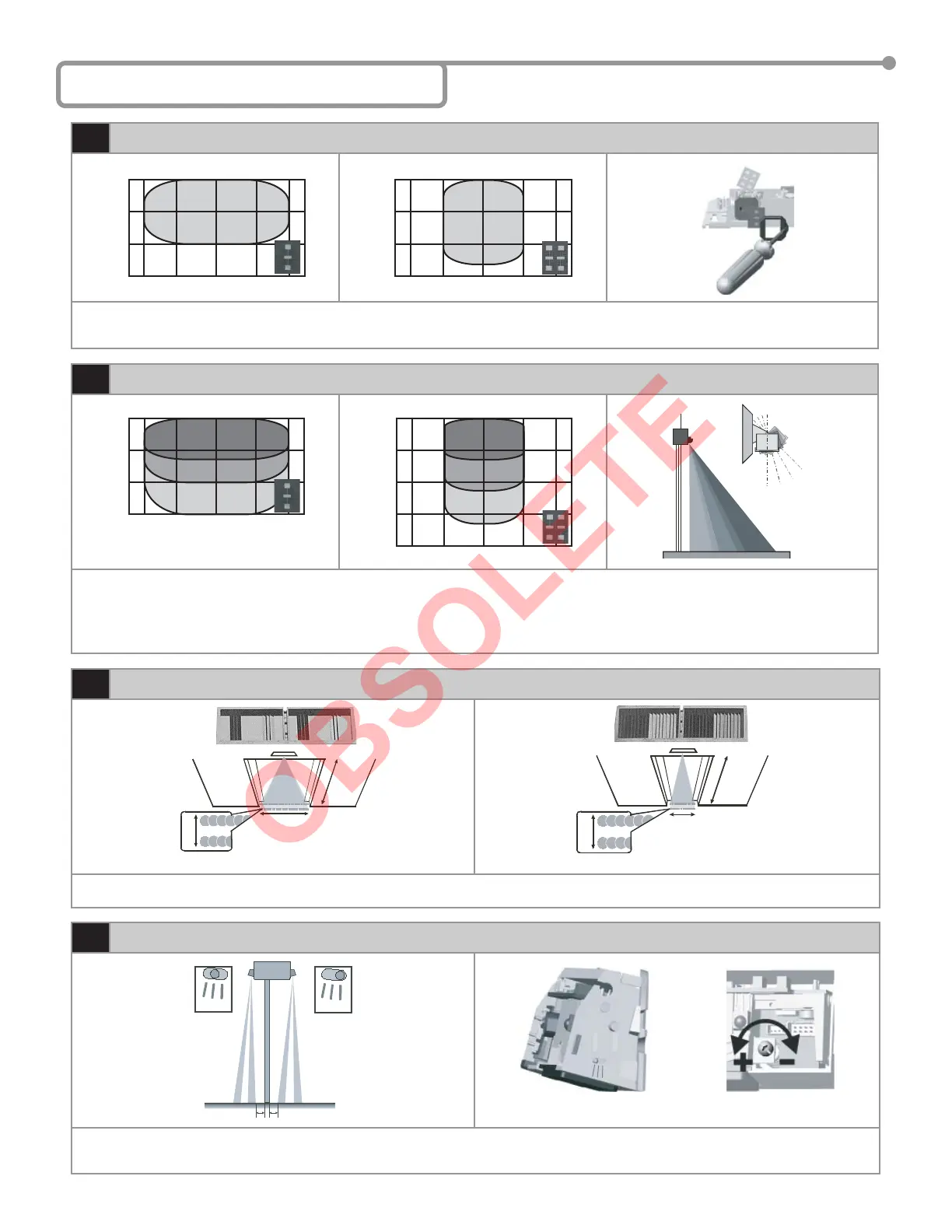
Radar Motion Sensing Field: Width
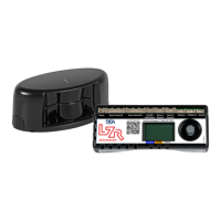
1. Insert the desired microwave antenna for a wide or narrow fi eld of detection. The optional narrow fi eld antenna is located in the slot behind
the mounted antenna as shown. To remove the antenna, carefully remove the protective cover and change the antenna. Once the proper
antenna is in place, adjust the angle of antenna as necessary.
0 3.2’ 6.4’3.2’6.4’
0
3.2’
6.4’
9.6’
0 3.2’ 6.4’3.2’6.4’
0
3.2’
6.4’
9.6’
Wide Pattern
Narrow Pattern
2
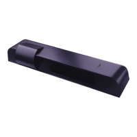
Radar Motion Sensing Field: Depth
1. The position of the sensing fi eld is determined by the vertical angle of the planar antenna. The angle is adjusted by gently rotating the
antenna forward or backward. The default angle is 30°.
2. The tilt angle is determined by the position of the sensor with relation to the face of the door. A 15° angle will result in the pattern being drawn
back toward the door. A 45° angle will place the pattern further away from the door. Be certain to walk test the detection fi eld and ensure
compliance with applicable ANSI standards.
0 3.2’ 6.4’3.2’6.4’
0
3.2’
6.4’
9.6’
0 3.2’ 6.4’3.2’6.4’
0
3.2’
6.4’
9.6’
13.1’
15°
30° 45°
30°
45°
15°
0°
3
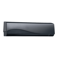
IR Presence Sensing Field: Width
1. Install the lens for the desired IR pattern. The wide pattern offers 2 curtains of 24 overlapping spots and the narrow pattern offers 2 curtains of
12 overlapping spots. When installing the lens ensure the smooth part of the lens is installed facing outward.
6.5’
14”
7.2’
3.2’
14”
7.2’
Wide Pattern Narrow Pattern
4
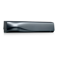
IR Presence Sensing Field: Depth
1. The IR pattern may be adjusted by moving the pattern nearer or further away from the face of the door by adjusting the tilt angle from +4° to
-4°. A counterclockwise rotation of the adjustment screw will move the curtain further away from the door and clockwise rotation will move the
curtain toward the door. Precise location of the IR beam may be found by using BEAs Spotfi nder P/N 10SPOT.
-4°
0°
max. 3” max. 3”
+4°
-4°
0°
Sensor Plastic Pin Indicator Sensor Adjustment Screw
Page 4 of 13 75.5122.05 20070427