EasyManua.ls Logo

BEA WIZARD SMR User Manual

BEA WIZARD SMR
17 pages
To Next Page IconTo Next Page
Page #1 background imageLoading...
Page #1 background image
75.0127 V3 Jul. 2003 [Rev. 8/13/2004]
Page 1 of 17
COMBINED
SAFETY &
ACTIVATION
SENSOR
TECHNICAL
SPECIFICATIONS
USERS GUIDE WIZARD SMR
COMBINED ACTIVATION & SAFETY SENSOR
The Wizard SMR (PN:10WIZARDSMR) combines k-band microwave and focused active infrared technology to provide
superior activation and safety for an automatic sliding door system. For activation, the unit provides digitally processed and
sophisticated motion tracking technology for unidirectional sensing when energy conservation is critical. For safety, the unit
emits 2 rows of 24 beams of focused presence technology that provides extraordinary safety. The active infrared remains
active even when the door is closing. Serial numbers 52000 and greater provide the added ability for an “ALL RELAY” output,
making it compatible with older non-microprocessed control boxes.
DESCRIPTION SPECIFICATION
Supply voltage 12 to 24 VAC / VDC: -5% to +10%
Power frequency 50 / 60 Hz
Power consumption < 3 W
Mounting height
Standard
High
5’9” to 8’2”
8’2” to 13”
SMR data input 10 to 30 V DC
Delay of the output activation after stimulation
transistor : < 1ms
3-color LED
RED : presence detection
GREEN : motion detection
ORANGE :monitoring process
Temperature range -30°F to +131°F
Degree of protection NEMA 3S / (IP54)
Product conformity R&TTE 1999/5/EC & EMC 89/336/EEC
BZT Germany, TÜV
Dimensions 10.4 " x 2.2 " x 1.9 "
Weight .55 lbs / 250 g
Housing material ABS & LURAN S
Color of Housing Anthracite gray (standard), aluminum or white finish
Cable length 8’ of six-conductor cable
MOTION SENSOR PRESENCE SENSOR
Technology Microwave and microprocessor
Transmitter frequency :24.125 GHz
Transmitter radiated power : <20 dBm EIRP
Transmitter power density : < 5 mW/cm²
Focused active infrared and
Self-monitored microprocessor
Spot diameter (standard) : 4” max
Number of spots : 24 or 12 spots by
curtain
Number of curtains : 2
Detection field (standard)
Wide field
Narrow field
13’0” W x 6’6” D
6’6” W x 8’2” D
6’6” W x 13.75” D
3’3” W x 13.75” D
Detection mode Minimum detection speed
2 inches / sec. (measured in the sensor axis)
Response time : < 128ms
Angle : from 15° to 50° in elevation (adjustable) from - 4° to + 4° (adjustable)
Output specification Relay (free of potential change-over contact) :
Max contact voltage : 42V AC/DC
Max contact current : 1A (resistive)
Max switching power : 30W (DC) / 60VA (AC)
Transistor (optocoupled transistor)
Max output current : 100 mA
Max switching power : 48 V DC
Output hold-time 0.5s to 9s (adjustable) 1s (fixed)
Manual adjustment
orientation of sensing field (mechanically)
shape of the sensing field (choice of antenna)
multiple functions (using push buttons).
orientation of sensing field
shape of the sensing field (choice of
front lens)
multiple functions (by push buttons).
Remote control adjustments
Sensitivity.
Hold time.
Detection mode.
Immunity
Output configuration.
Sensitivity.
Auto-learn time
Monitoring mode
Number of Curtains
Relay / Transistor configuration
Rain Mode
Snow Mode
We open up New Horizons
OBSOLETE
Question and Answer IconNeed help?

Do you have a question about the BEA WIZARD SMR and is the answer not in the manual?

BEA WIZARD SMR Specifications

General IconGeneral
Detection AreaAdjustable
TechnologyMicrowave
Detection ModeMotion
OutputRelay
Humidity RangeUp to 95% non-condensing
Dimensions120 mm x 80 mm
Weight200g
Alarm OutputRelay output
TypeMicrowave and Microprocessor Based Motion Sensor

Summary

Technical Specifications

Power and Environmental Specifications

Covers supply voltage, power, temperature, and protection ratings.

Physical and Material Specifications

Details dimensions, weight, housing material, and cable type.

Motion Sensing Technology and Field

Explains microwave technology, frequency, and detection field parameters.

Presence Sensing Technology and Field

Explains infrared technology, beam patterns, and detection characteristics.

Output and Adjustment Settings

Covers output specifications, hold time, and adjustment options.

Component ID and Safety

Component Identification

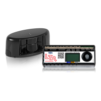
Identifies the main parts of the sensor unit.

Safety Precautions

Lists essential safety measures for handling and installation.

Mechanical Installation Steps

Provides step-by-step instructions for physically mounting the sensor.

Electrical Installation and Wiring

Wiring to Microprocessed and Old Style Controls

Explains specific wire connections for different control types.

Wiring Notes and Examples

Provides additional wiring guidance and configuration examples.

Mechanical Adjustments for Motion Sensing

Sensing Field Patterns and Angles

Explains how antenna angle affects detection field size and shape.

Mechanical Adjustments for Presence Sensing

Infrared Presence Field Adjustment

Describes how to adjust the proximity and width of the infrared beam.

Universal Remote Control Overview

Wizard SMR Programming - Locking & Unlocking

Wizard SMR Programming - Inquiring Settings

Wizard SMR Programming - Key Parameters

Radar Sensitivity Adjustment

Controls the sensitivity level of the motion detection.

Relay Hold Time Configuration

Sets the duration the output relay remains active after detection.

Wizard SMR Programming - Output and Modes

Output Configuration Options

Defines the type and state of the sensor's output signals.

Auto-Learn Time Setting

Configures the time for the sensor to adapt to its environment.

Radar Detection Mode Selection

Selects between bi-directional, uni-directional, and MTF modes.

Immunity and Infrared Sensitivity

Adjusts immunity to disturbances and infrared detection sensitivity.

Radar Mounting Height and SMR Mode

Sets mounting height parameters and enables/disables SMR mode.

Wizard SMR Programming - Special Modes

IR Curtain Function Control

Manages the activation and deactivation of the secondary IR curtain.

Door Control Function Modes

Selects the operational logic for the automatic door.

Rain Mode Configuration

Optimizes sensor performance during rainy conditions.

Snow Mode Configuration

Optimizes sensor performance during snowy conditions.

Manual Set-Up Without Remote Control

Resetting Unit to Factory Defaults

Procedure to restore all settings and codes to their original factory values.

Customizing Settings Mode

Explains how to enter and navigate the sensor's customization menu.

Parameter Customization Guide

Details how to alter parameter values using the buttons and LED feedback.

Manual Configuration Parameter List

Lists all configurable parameters with their values and default settings.

Manual Set-Up And Power-Up Procedures

Manual Set-Up Example

Illustrates a practical example of changing sensor settings manually.

Power-Up Sequence and LED Status

Describes the expected LED behavior during power-up and set-up.

Troubleshooting Common Issues

Troubleshooting Detection and Door Operation

Red LED Status Indicators

Solves problems indicated by the red LED status.

Door Opening and Closing Faults

Diagnoses and resolves issues causing doors to open or fail to close.

Red LED Off and Door Operation Faults

Troubleshoots when the red LED is off and doors do not operate correctly.

Door Cycling and Detection Issues

Resolves problems with doors repeatedly opening or failing to detect.

Troubleshooting Remote and Motion Response

Remote Control and Unlock Issues

Addresses problems with the remote and access code entry.

Set-up and Motion Response Problems

Troubleshoots rapid flashing LEDs during set-up and lack of motion response.

Optional Accessories

Company Contact Information

Addendum 1: Stanley Duraglide Integration

Stanley Duraglide Wiring Diagram

Presents the specific wiring connections for the Stanley Duraglide system.

Addendum 2: Besam CUJ-9 AMD II Integration

Besam CUJ-9 AMD II Wiring Diagram

Provides the wiring diagram and notes for Besam CUJ-9 AMD II systems.

Addendum 3: Besam Uni-Slide Integration

Besam Uni-Slide Wiring Diagram

Presents the specific wiring connections for the Besam Uni-Slide system.

Addendum 4: Dor-O-Matic 96K Integration

Dor-O-Matic 96K Wiring Diagram

Provides the wiring diagram and notes for Dor-O-Matic 96K systems.

Addendum 5: Horton C2150 Control Integration

Horton C2150 Control Wiring Diagram

Presents the specific wiring connections for the Horton C2150 control system.

Related product manuals