75.0127 V3 Jul. 2003 [Rev. 8/13/2004]
Page 4 of 17
MECHANICAL
ADJUSTMENTS
ADJUSTMENTS
MOTION SENSING
FIELD
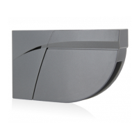
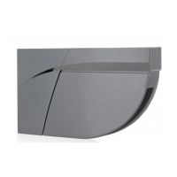
1. The position of the sensing field is determined by the vertical angle of the planar antenna. The angle is
adjusted in 3° increments by gently rotating the antenna forward or back. The default mounting angle is 30° -
Patterns shown in diagram below are those at 30°.
2. The tilt angle will be greatly determined by the position of the sensor with relation to the face of the door. A 15º
angle will result in the pattern being drawn back towards the door, where as the 45º will place the pattern
farther away. Be certain to walk-test detection field and insure compliance with current applicable ANSI
standards.
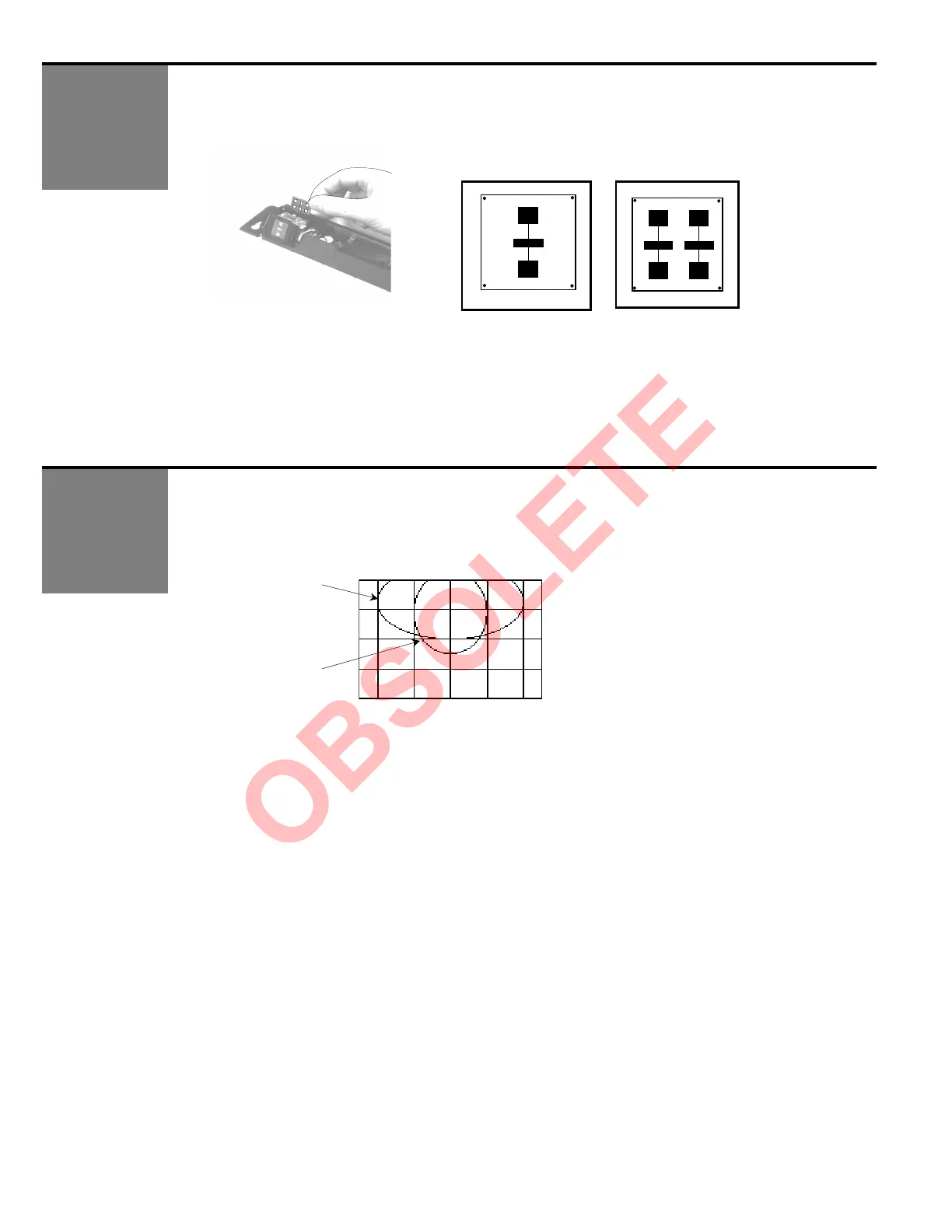
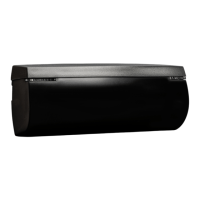
1. Insert the desired microwave planar antenna for a narrow or wide field of detection. Refer to the
diagram below for approximation of field size for each pattern.
7’-0” height = [13’ (W) X 6’ 6” (D)] [6 6” (W) X 8’ 2” (D)]
• The optional narrow-field antenna is located in a slot behind the mounted antenna as shown.
• To remove the antenna, carefully remove the protective cover and change antenna.
• Once proper antenna is in place, adjust angle of antenna as necessary.
WIDE NARROW
6.4’ 3.2’ 0 3.2’ 6.4’
0
3.2’
6.4’
9.6’
Wide Pattern
Narrow Pattern