75.0127 V3 Jul. 2003 [Rev. 8/13/2004]
Page 7 of 17
WIZARD SMR
PROGRAMMING
GUIDE – Cont.
OUTPUT
CONFIGURATION
The Output configuration has 4 possible
output values:
1 = N.O. relay, N.C. transistor
2 = N.C. relay, N.O. transistor
3 = N.C. relay, N.C. transistor
4 = N.O. relay, N.O. transistor
5 = All Relay Output (N.O.)
6 = All Relay Output (N.C.)
4
After pressing the OUTPUT
CONFIGURATION key, the red LED
flashes quickly. After pressing a
number button, the red LED flashes
slowly. (N.O. indicates relay closure
upon detection and power-off would
result in an open relay).
Values 5 & 6 available on SN: 52000
and greater
-LEARN The Auto-Learn time enables the Wizard to
adapt to new permanent changes within its
field of detection, after the set time (below)
expires. Once expired, the Wizard will
return to a state of non-detection.
1
0 = 30 seconds 4 = 10 minutes
1 = 1 minute 5 = 15 minutes
2 = 2 minutes 6 = 20 minutes
3 = 5 minutes 9 = Infinity
-LEARN key,
the red LED flashes quickly. After
pressing a number button,
flashes slowly.
Note: Value 9 (infinity) available on
SN: 60000 and greater
RADAR
DETECTION
MODE
Detection mode offers 3 different levels of
detection: Bi-directional, Uni-
Uni-directional with MTF (motion tracking
feature). MTF allows the Wizard to switch
from uni-directional to bi-directional upon
detection from the normal approach
3
1 = Bi-directional
2 = Uni-directional
3 = Uni-directional with MTF
After pressing the DETECTION MODE
key, the red LED flashes quickly. After
pressing a number button, the red LED
flashes slowly.
IMMUNITY
(motion)
Immunity reduces the influence of un
disturbances within the field of motion
detection, without reducing the pattern.
1 = Extreme sensitivity
2 = Normal Sensitivity
3 = Reduced sensitivity
2
After pressing the IMMUNITY key, the
red LED flashes quickly. After pressing
a number button, the red LED flashes
slowly.
INFRARED
SENSITIVITY
Infrared sensitivity reduces the influence of
unwanted disturbances within the field of
presence detection.
1 = Low sensitivity – hi gloss floors
2 = Normal sensitivity
2
After pressing the INFRARED
SENSITIVITY key, the red LED flashes
quickly. After pressing a number
button, the red LED flashes slowly.
RADAR
MOUNTING
HEIGHT
0 = launch infrared set-up (learn
background).
1 = Microwave at normal mounting
height
2 = Microwave at high mounting
height (8’ 2” to 13’)
3 = Restore all parameters to
default value. SN less than 52000
9 = Same as value 3, but only for
SN 52000 and greater.
1
After pressing the INFRARED
SENSITIVITY key + 0, the red / green
LED flashes to indicate set-up.
After pressing the INFRARED
SENSITIVITY key + 1, 2, or 3
the red LED will flash slowly.
SMR
SMR (Self-Monitoring Ready) mode is
enabled for the use with BEA’s DCU (Door
Control Unit). It is disabled for all other
applications. The DCU sends & receives
monitoring signals to the sensor when this
feature is enabled. The DCU can then take
control of a door in the event of a sensor
failure.
0 = SMR Input OFF
1 = SMR input ON
0
After pressing the SMR key, the red
LED flashes quickly. After pressing a
number button, the red LED flashes
slowly.
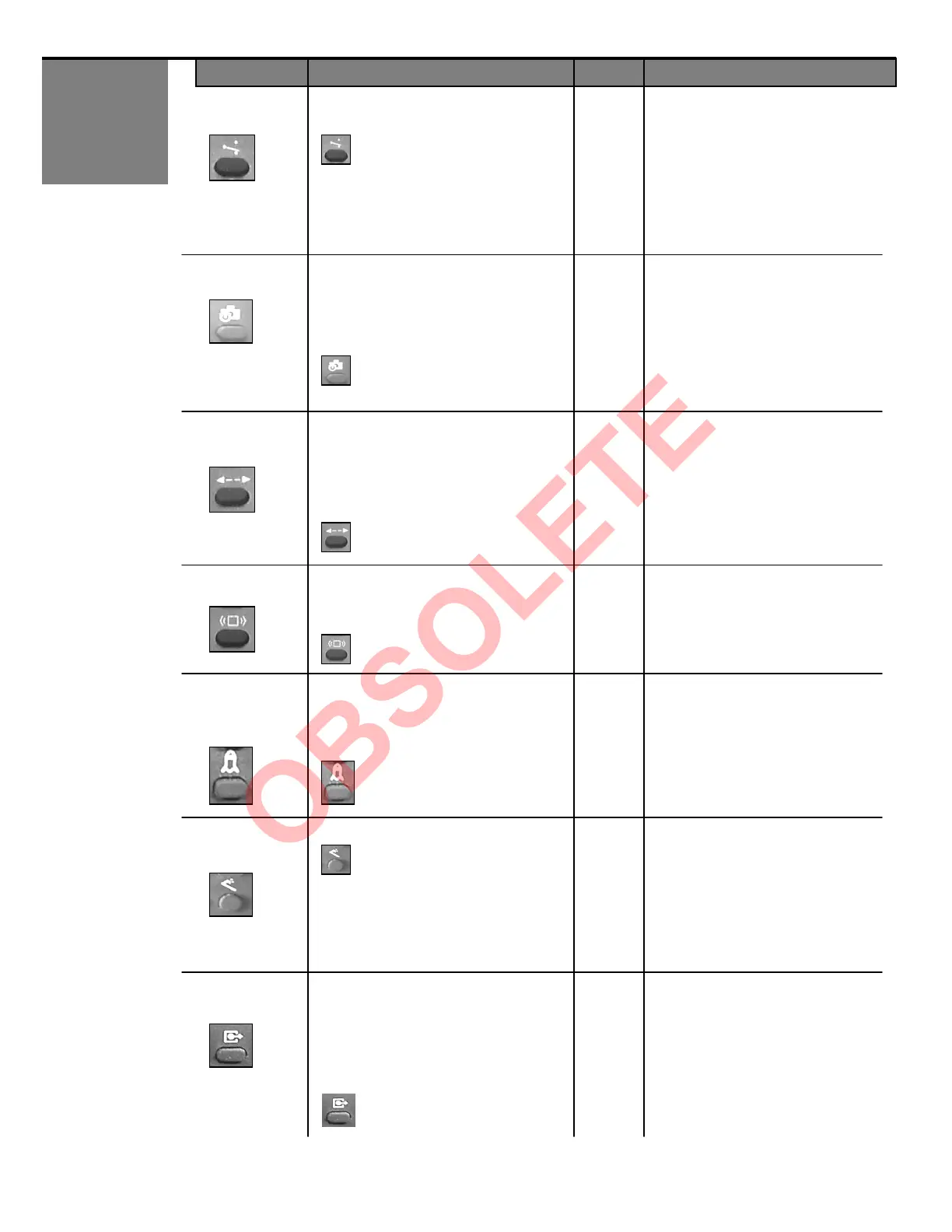
KEY USER’S ACTIONS DEFAULT LED STATUS