21
Emergency Reserve Manifold
2005715.05
6.2 Replace Sampling Outlet (See
table 6 for part numbers)
Table 5 : Sampling Outlet Part Numbers
GAS Type 1st Fix 2nd Fix
Oxygen (O2) 2005810 1826850
Nitrous Oxide (N2O) 2005811 1826851
Oxygen/Nitrous Oxide (O2/
N2O)
2005812 1826852
Medical Air 2005813 1826853
Surgical Air 2005814 1826854
Nitrogen (N2) 2005816 2004835
Carbon Dioxide (CO2) 2005815 2004836
6.2.1 The Sampling outlet can be worked on
without taking the ERM o line.
6.2.2 Ensure the sampling outlet isolation valve
‘C’ is closed (as shown in gure 17).
6.2.3 Probe the outlet to depressurise.
6.2.4 To replace the whole outlet, disconnect
the 1/2” connection and remove the 2 x M4 cap
head set screws. Ensure the replacement unit is
the correct gas type. Replace the new outlet by
connection the 1/2” connection ensure the O-ring
is in place (Replace if damaged, see gure 17 for
part number. Secure the unit with the M4 cap
head and washers.
6.2.5 For replacing the 2nd x only (see gure
17). Press the fascia ring clips shown and slide
it from the release ring. Press the release ring,
compressing the locking spring until the roller pips
fall out. Remove the 2nd x fasteners and slide of
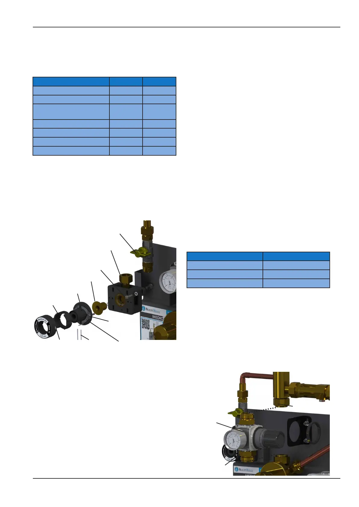
Figure 17 - Sampling Outlet Replacement
1 x 1/2” at face connection
with swivel nut and O-ring seal
(Seal P/N: 1823637)
Isolation Valve ‘C’
(Shown in closed position)
Fascia ring clips
Release ring
Roller Pins Locking spring
1st x fastener
2nd x
fastener
Check Valve
Gas specic
the 2nd x and check valve capsule.
Fit the new check valve, gas specic socket and
locking spring. Secure in place with the 2nd x
spring. Ensure the spring can be compressed
without catching the sides of the gas specic
socket, adjust as required. Fit the release ring and
compressing the locking springs till the roller pins
can be tted, then release. Fit the fascia ring so
that the clips are secured.
6.2.6 After replacing the sampling outlet
(entire outlet or just the 2nd x) probe the outlet
to ensure the locking mechanisms functions
correctly.
6.2.7 Open valve ‘C’ and check for leaks. If leaks
are found, before attempting to rectify close valve
‘C’ and probe the outlet to depressurise. Repair
the leak and repeat steps in 6.2 as required.
6.2.8 Close valve ‘C’ when replacement
complete.
6.3 Replace 2nd stage regulator
(See table 7 for part numbers)
Table 6: 2nd Stage Regulator Part Numbers
Regulator Nominal Pressure Part Number
4 Bar 2005689
7 Bar 2005690
11 Bar 2005691
6.3.1 Complete steps in section 6.1 before
carrying out any component replacement on the
ERM.
6.3.2 Slowly turn the swivel nut of the top 1”
connection. If the you hear gas escaping do not
fully unscrew the joint until the system is fully
drained.
Locking Nut
2nd Stage
Regulator
2 o 1/2” BSP
x 1” Flat face
connector with
O-ring (2000152)
and bonded seal
(1825637)
Figure 18 - 2nd Stage Regulator Replacement