23
Emergency Reserve Manifold
2005715.05
6.5.5 Taking care not to damage the O-ring seals
replace the new relief valve as shown in gure 20,
and fasten the 2 at face joints.
6.5.7 Follow steps in section 6.11 bring the ERM
back online.
6.6 Replace 1st stage relief valve
(P/N: 2005384)
6.6.1 Complete steps in section 6.1 before
carrying out any component replacement on the
ERM.
6.6.2 Disconnect the 3/4” and 1” swivel nut
connection on the exhaust line to ensure adequate
space for removing the valve without spraining the
pipe work (as shown in gure 21).
6.6.3 Start to unscrew the 1st stage relief valve,
if you hear gas escaping do not fully remove until
the system is fully drained.
6.6.4 Inspect the existing seals and replace if
required, see gure 21 for seal part numbers.
6.6.5 Taking care not to damage the O-ring seals
replace the new relief valve as shown in gure 21,
and fasten the 2 exhaust pipe at face joints.
6.6.6 Follow steps in section 6.11 bring the ERM
back online.
6.7 Replace High Pressure Bank
Valve (P/N: 2005820)
6.7.1 Complete steps in section 6.1 before
carrying out any component replacement on the
ERM.
6.7.2 Slowly turn 1 of the 5/8” swivel nut
connections. If the you hear gas escaping do not
fully unscrew the joint until the system is fully
drained.
6.7.3 Fully disconnect the two 2 joints as shown
in gure 22 and gently remove the unit by sliding it
towards you. Take care not to damage the seals.
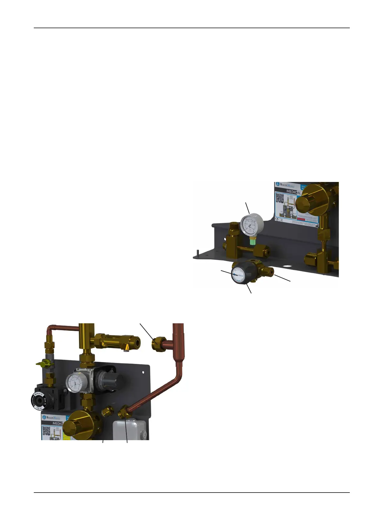
Figure 21 - 1st Stage Relief Valve Replacement
1” at face connections with
swivel nut and O-ring seal
3/4” at face connections
with swivel nut and
O-ring seal
1st Stage Safety Relief Valve
Bonded seal (1824977)
O-ring seal (2000179)
2 x 1/4” x 5/8” at face
connections
O-ring seal (1822236)
Bonded seal (2004808)
1/4” blanking plug
Bonded Seal (2004808)
High
Pressure
Isolation
Valve
Contact Gauge
Sealing washer (2005765/7)
Figure 22 - Cylinder Bank Valve Replacement
6.7.4 Remove the two 1/4” x 5/8” BSP ttings,
blanking plug and contact gauge from the
old valve. Take note of the direction label on
the underside of the base of the valve, t the
connectors and gauge as per the old valve unit.
Inspect the existing seals and replace if required,
see gure 22 for seal part numbers.
6.7.5 Taking care not to damage the O-ring seals
replace the new valve as shown in gure 22, and
fasten the 2 at face joints.
6.7.6 Fully open the valve unit and stick the label
onto the handle so the “BeaconMedæs” logo is
horizontal
6.7.8 Follow steps in section 6.11 bring the ERM
back online.