8
Emergency Reserve Manifold
2005715.05
2. Installation
2.1 Installation procedure for
Panel.
CAUTION: Ensure no contaminates, oil
or grease come into contact with any of the gas
connection/internals.
2.1.1 Unpack and inspect all items for damage.
2.1.2 Check wall for suitability.
CAUTION:Suppliedxingsareforuse
with solid masonry walls only. Alternative
xingtypesarenotsuppledwiththeunit.For
securing to alternative wall types, ensure that
1.6 Halogen Free Components
The ERM contains NO HALOGENATED polymers
located in the gas stream that may experience
pressurised oxygen in excess of 3000 kPa (30 Bar)
in normal operation or single fault condition, as
recommended for safe practise of the medical gas
pipeline system.
wall structure and selected fasteners are suitable
for supporting the 16 kg weight of the ERM.
2.1.3 Identify the centre position of the ERM on
the wall and mark.
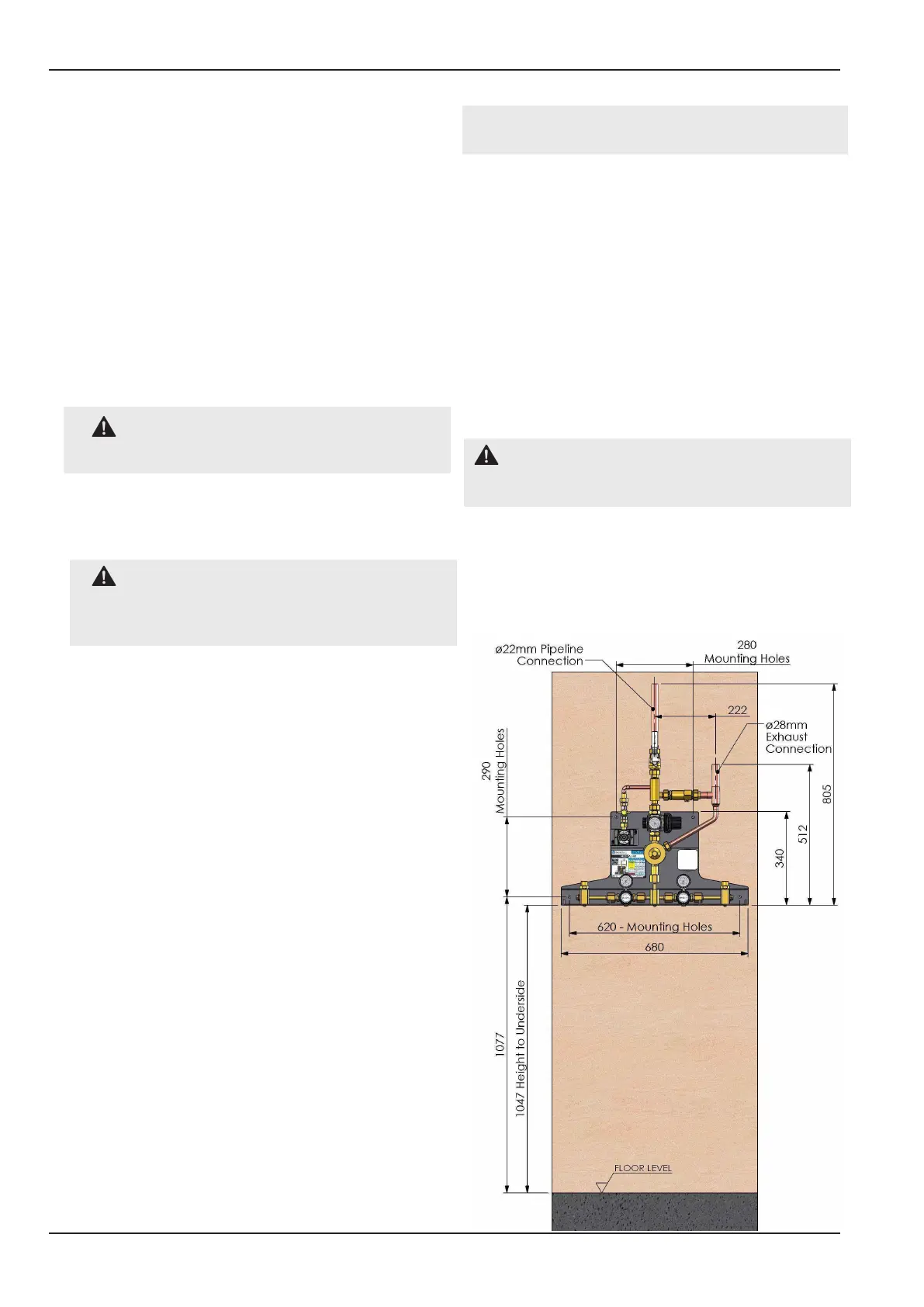
2.1.4 Drill wall and t wall plugs. Screw the ERM
to the wall, checking that it is rmly attached. See
gure 3 & 4 for typical mounting heights.
2.1.5 Loosely connect the supplied ø22mm OD
stub pipe (Item 12, gure 1) to the main pipeline
isolation valve (Item 9, gure 1). Do not t the
O’ring seal till after brazing.
2.1.6 Braze the pipework using the uxless
brazing technique with nitrogen purge.
CAUTION: Ensure the brazed connection
point is isolated from any other pipeline source
of supply.
2.1.7 Undo the securing nuts on the stub pipes
and insert the ‘O’ ring supplied into the connection
grooves and tighten.
Figure 3 - Typical Installation For Use With ‘J’ &
‘G’ Type Cylinder