16
Emergency Reserve Manifold
2005715.05
3. Commissioning
3.1 General
Commissioning of the ERM must be carried
out in full after initial installation. The object of
the commissioning procedure is to ensure that
all components are serviceable and that the
overall system is operable and set to the correct
distribution pipeline pressure. Suitably qualied
competent personnel who are familiar with this
manual must only undertake commissioning of the
ERM.
3.2 Preparation
3.2.1 Ensure that all tailpipes are connected to
the cylinders and manifolds on both sides and
that the restraint chains are secure around the
cylinders.
3.2.2 Ensure that the outlet pipe from the ERM is
connected to the distribution system of the same
gas service, downstream of the main supply unit
and isolation valve ‘A’ (shown in gure 2).
3.2.3 Ensure that the ERM isolation valve ‘B’
(shown in gure 1) is tted and in the closed
position.
3.2.4 Open all cylinder valves on the ERM.
3.2.5 Fully open the high-pressure isolation
valves 1 and 2 (shown in gure 1).
3.2.6 Check connections on the headers,
tailpipes, regulator and associated pipework for
leaks.
3.2.7 Fully close the right-hand high-pressure
isolation valve 2 (gure 1 & 2).
3.3 Pressure Checks
3.3.1 Ensure that full gas cylinder pressure is
shown on the cylinder contents gauges (Fitted to
valve 1 & 2, see gure 1).
3.3.2 With Valve ‘B’ closed and valve ‘C’ open,
exhaust a quick blast of gas from the sampling
outlet, close valve ‘C’. Check that the pressure on
the pipeline distribution pressure gauge is typically
as per table 4. Adjust as necessary.
Note...For reducing the pressure set point, ensure
valve ‘B’ is closed and sampling outlet isolation
valve ‘C’ is open. Gently bleed the gas from the
sampling outlet while making adjustments, as the
4. Principles of Operation
4.1 General
The ERM line pressure is set below the normal
operating range of the primary supply. While the
primary supply is functioning within it’s design
limits, the ERM will not feed gas into the pipeline.
If the primary supply fails, causing the pipeline
pressure to fall to the ERM’s set point it will
automatically start feeding gas to the pipeline.
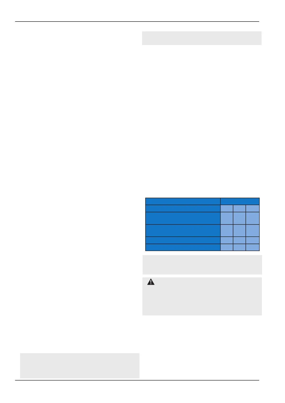
Table 3: Typical pressure settings for HTM02-
01 primary and emergency medical gas
supply system, during normal pipeline system
operation.
Pressure (Bar)
Nominal System Design 4 7 11
Max. Static Pressure Primary
Supply
4.6 8.2 11.5
Min. Dynamic Pressure Primary
Supply
4.2 7.4 10.3
Max. Static Pressure ERM 4.0 7.2 10.0
Min. Dynamic Pressure ERM 3.5 6.5 9.0
Note - Table 4 shows typical examples. These
gures may dier depending on the hospital’s
pipeline management policy.
CAUTION: It would be recommended to
set the ERM line pressure at least 0.2 bar below
the main supply source pressure at full design
owtoensuretheemergencymanifolddoes
not supply the pipeline during normal primary
source operation.
The recommended setup of the ERM is to have the
left hand bank open and ready to come online and
the right hand bank closed.
In the event of the primary system failing to
supply (Awareness of the Primary supply failure is
typically from central alarm system) the ERM line
regulator (see gure 1) can be manually increased
to match the primary supply’s nominal values, so
that the full distribution pressure is restored.
regulators is a none relieving type. Always leave
valve ‘C’ closed when nished.
3.3.3 Check that the line pressure does not vary
outside of the requirements of the installation
(see table 4, Section 4 - Principle of Operating, for
typical values).
3.3.4 Complete the steps in section 4.2 -
Procedure to prime ERM, to bring the ERM online.