20
Emergency Reserve Manifold
2005715.05
6.0 Component Replacement
Procedures
WARNING: IT IS ESSENTIAL THAT ONLY
GENUINE BEACONMEDÆS SPARE PARTS ARE
FITTED DURING MAINTENANCE.
CAUTION: Ensure no contaminates, oil
or grease come into contact with any of the gas
connection/internals.
Preparation For Component Re-
placement
6.0.1 Ensure the main gas supply system is
functioning correctly and supplying the pipeline.
6.0.2 Close the ERM line isolation valve ‘B’ (See
gure 1). Close all the cylinder and open both
bank valves (see gure 1 and 2).
5.3.9 Open Valve ‘C’ and carefully bleed gas from
the sampling outlet.
5.3.10 Observe the falling pressure on the contact
gauge.
5.3.11 When the pressure falls to 14 bar for 100
bar scale, and 68 bar for the 315 scale gauges the
contact will provide an open signal, initiating a
“Reserve Low” alarm on the primary alarm system.
Should this not occur replace the contact gauge
(See section 6.10).
5.3.12 Repeat steps 5.3.8 to 5.3.11 for the
opposite contact gauge. Close valve ‘C’ when
nished.
5.3.13 Finally, tighten all joints, open all cylinder
valves and perform a leak test on all joints.
5.3.18 Perform the steps in section 4.2 -
Procedure to prime ERM.
5.3.19 The ERM is now ready for use.
5.4 5 Years
Replace the pressure safety valve for a new
certied relief valve, see sections 6.4 & 6.5.
5.5 As Required
Replace tailpipes, pressure safety valve, pressure
regulator, high-pressure isolation valve, isolation
valves, contact gauges, non-return valve etc. as
and when required (see section 6.0 to 6.10).
6.0.3 Open the sampling outlet valve ‘C’, and
probe the outlet to depressurise the system.
CAUTION:Whenexhaustinganaesthetic
andoxygenmanifoldsensurethatthemanifold
room is well ventilated and no potential ignition
sources are present.
Note - If the cylinder contents gauges are not
rapidly dropping in pressure, stop draining the
system and check all cylinders are correctly
isolated.
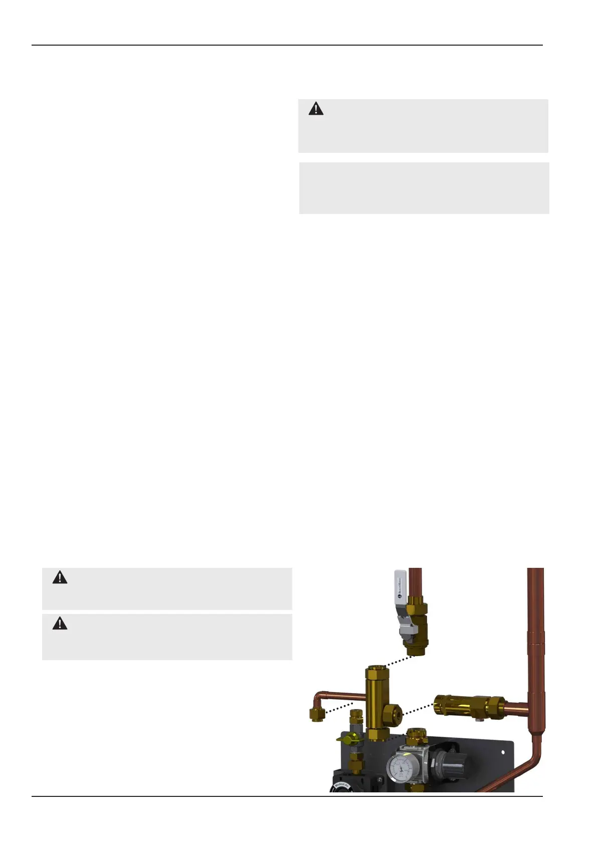
6.1 Replace line non-return valve
(P/N: 2005778)
6.1.1 Complete steps in section 6.1 before
carrying out any component replacement on the
ERM.
6.1.2 Slowly turn the swivel nut of the top 1”
connection. If the you hear gas escaping do not
fully unscrew the joint until the system is fully
drained.
6.1.3 Fully disconnect all 4 joints as shown in
gure 16 and gently remove the unit by sliding it
towards you. Take care not to damage the seals.
6.1.4 Inspect the existing seals and replace if
required, see gure 16 for seal part numbers.
6.1.5 Taking care not to damage the O-ring seals
replace the new non-return valve as shown in
gure 16, and fasten the 4 at face joints.
6.1.6 Follow steps in section 6.11 bring the ERM
back online.
Figure 16 - Line Non-return Valve Replacement
3 x 1” at face
connections with swivel
nut and O-ring seal
(Seal P/N: 2000152)
1 x 1/2” at face
connection with swivel
nut and O-ring seal (Seal
P/N: 1823637)