25
Emergency Reserve Manifold
2005715.05
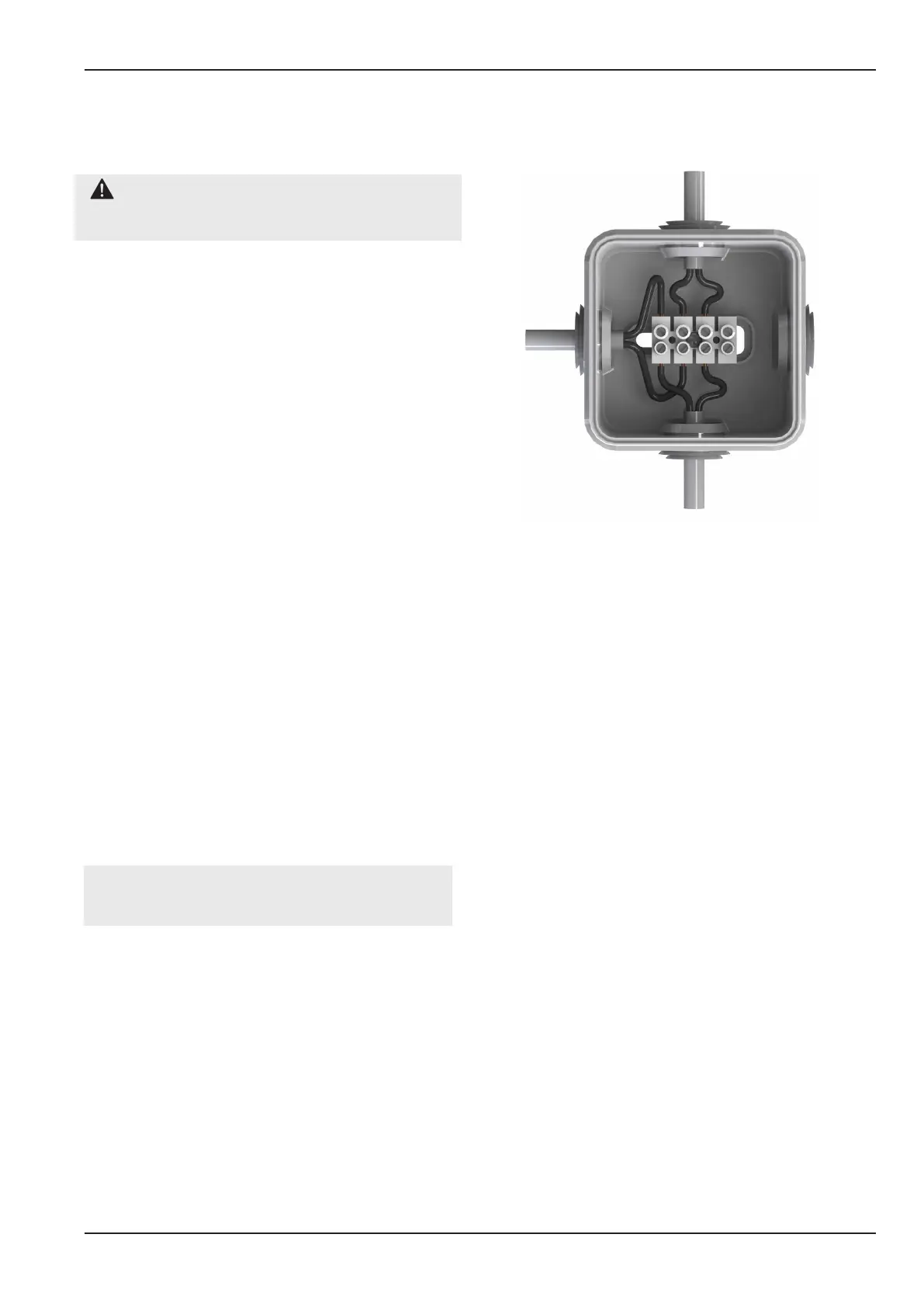
Figure 25 - Reserve Low Contact Gauge Alarm
Wiring
Left bank
contact gauge
1
2
2
1
3 4
3 4
Right bank
contact gauge
5 6
5 6
To primary supplies
“Reserve Low” alarm input
Note - 14 bar switch point typically used on N2O
and CO2. 68 bar switch point typically used for O2,
O2/N2O, Medical Air, Surgical Air and N2O.
CAUTION: Ensure the new gauge has the
same scale and alarm contact as the one being
replaced.
6.10.1 Complete steps in section 6.1 before
carrying out any component replacement on the
ERM.
6.10.2 Disconnect the contact alarm wire, see
gure 25.
6.10.3 Start to unscrew the line pressure gauge,
if you hear gas escaping do not fully remove until
the system is fully drained. If required disconnect
the high pressure bank valve to gain access to
the contact gauge (see section 6.7 - Replace High
Pressure Bank Valve, for procedure).
6.10.4 Replace the old seals with those supplied
with the new gauge.
6.10.5 Fit the new gauge as per the old unit
including wiring as per gure 25.
6.10.6 Follow steps in section 6.11 bring the ERM
back online.
6.11 Returning the ERM Back on-
line
6.11.1 After completing any repair work
on the ERM complete the step in section
3 - Commissioning, followed by section 4.2 -
Procedure to prime ERM.
Note - The panel may need to be purged as per
HTM 02-01 for UK installations, or as per relevant
standards if installed outside the UK.