Calibration and Adjustment Instructions for MC5 Multifunction Calibrator For Main Firmware Version 1.90
Page 11/16
Adjustment of Generation/Simulation Ranges
The accuracy of a generation range depends on the accuracy of the respective measurement
range. Therefore the measurement range should be adjusted before trimming the generation
range. Trimming the generation range affects the overshoot and damping of the generated
value.
Several of the calibrators generation range adjustment windows include the feedback measure-
ment value. This can be used for trimming the generation range. Using an external Digital Mul-
timeter is optional for these measurement ranges.
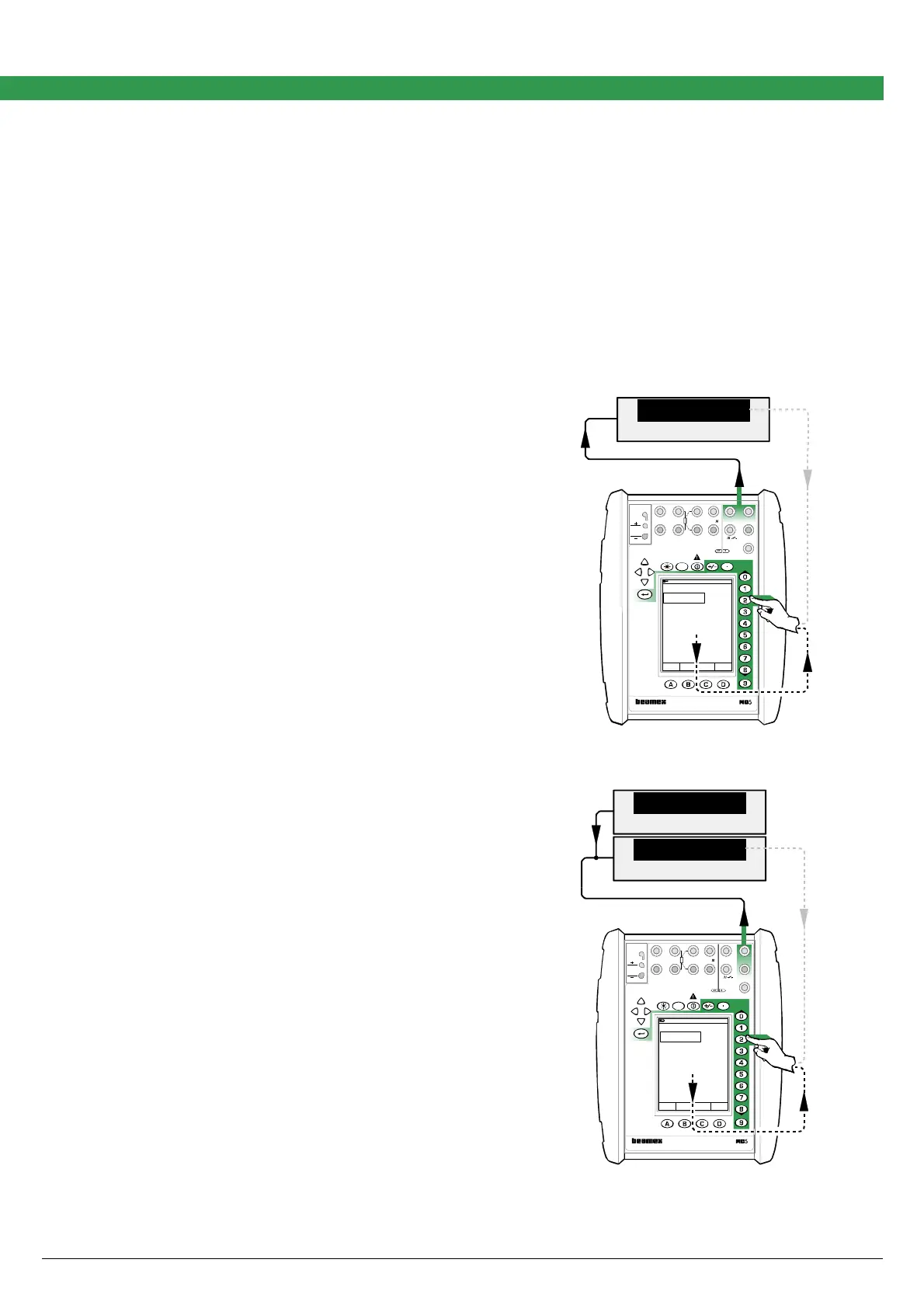
Adjusting the Current Generation in E Module (0 … 25 mA)
Quantity: Current
Function/Port: E: Current Source/Sink
Power supply needed for the current generation can be
provided either from the calibrator or from an external
power supply unit. The connection depends on the used
power supply.
The lowermost measurement value in the current gen-
eration window is the calibrator’s own feedback meas-
urement of the generated current. It is accurate enough
for trimming the generated value. The Digital Multimeter
connected to the loop is optional.
Power Supplied from the Calibrator
The uppermost picture defines the connection when the
calibrator provides the power supply.
External Power Supply
The lowermost picture defines the connection when an
external device is used for power supply.
Adjustment Procedure
The adjustment procedure is the same for both connec-
tions.
Adjustment point ranges, mA
Low: 0.5 … 5
High: 20 … 25
Move the field indicator to the uppermost field and enter
a current generation value that is inside the limits of the
low adjustment point range. Enter the correct current
seen on the Digital Multimeter’s display to Span Refer-
ence Value field in the calibrator. Then generate a cur-
rent that is inside the high adjustment point range and
enter the correct value for that point too. Repeat the low
and high adjustments until the current generation is ac-
curate enough.
When ready, select either another Quantity and Func-
tion/Port combination or save the adjustment result as
described in chapter Saving Adjustment Data on page
16.
DMM
mA
24.997 60
Field MENU
Calibration
Mode
17.10.2002 9:35
Current
E: Current Source/Sink
mA25.0000
Measurement mA
Span Reference Value 24.996
25.996
MULTIFUNCTION CALIBRATOR
T/C, Low V
4-w meas
R, RTD
3 & 4-w meas
V, I,
+24V
I
meas/sink
Low V
HART
®
T/C INT. RJ
T/C OR EXT
WIRES ONLY
2-w xmtr
V, ,
?
MEASURE
OUTPUTSENSOR MEASURE & SIMULATE
ET E
Max input:
60 VDC/30 VAC
Supply
DMM
V
mA
24.0
24.997 60
Field MENU
Calibration
Mode
17.10.2002 9:35
Current
E: Current Source/Sink
mA25.0000
Measurement mA
Span Reference Value 24.998
24.998
MENU
MULTIFUNCTION CALIBRATOR
T/C, Low V
4-w meas
R, RTD
3 & 4-w meas
V,
I
,
+24V I
meas/sink
Low V
HART
®
T/C INT. RJ
T/C OR EXT
WIRES ONLY
2-w xmtr
V, ,
?
MEASUREOUTPUTSENSOR MEASURE & SIMULATE
ET E
Max input:
60 VDC/30 VAC