Calibration and Adjustment Instructions for MC5 Multifunction Calibrator For Main Firmware Version 1.90
Page 12/16
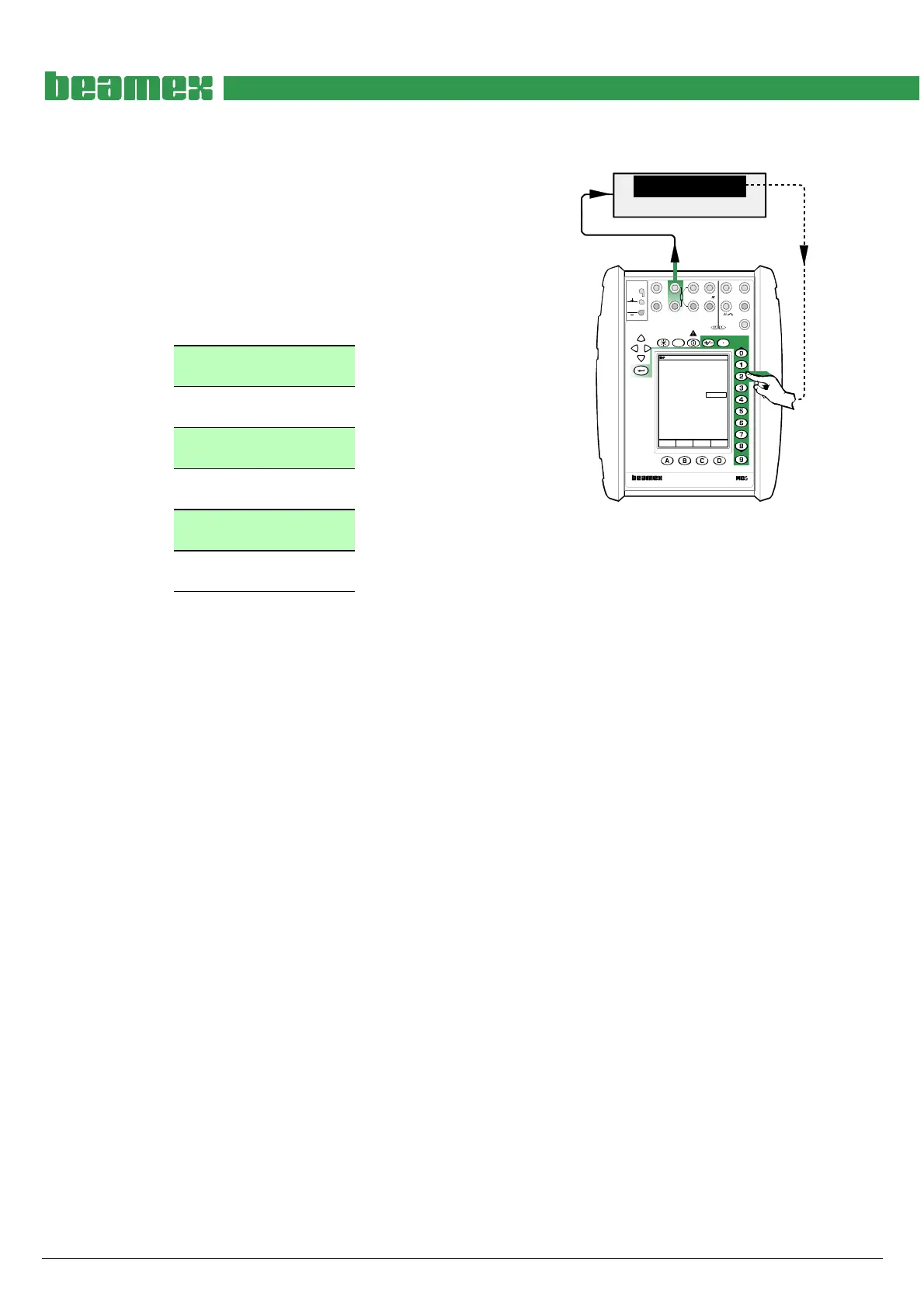
Adjusting the Resistance Simulation in ET Module (0 … 4000 ohm)
Quantity: Resistance
Function/Port: ET: Resistance Sim.
Connect an accurate Digital Multimeter to the calibra-
tor’s terminals highlighted in the adjacent picture.
The resistance simulation range is divided into
subranges that are adjusted as separate high and low
point pairs.
Adjustment points, ohm
Low 1: 1
High 1: 100
Low 2: 160
High 2: 250
Low 3: 300
High 3: 500
Low 4: 600
High 4: 1000
Low 5: 1200
High 5: 2000
Low 6: 2400
High 6: 4000
DMM
W
70.00103
17.10.2002 10:27
Resistance
ET: Resistance Sim.
W70.00
Span Reference Value 70.00103
Field MENU
Calibration
Mode
MULTIFUNCTION CALIBRATOR
T/C, Low V
4-w meas
R, RTD
3 & 4-w meas
V,
I
,
+24V I
meas/sink
Low V
HART
®
T/C INT. RJ
T/C OR EXT
WIRES ONLY
2-w xmtr
V, ,
?
MEASUREOUTPUTSENSOR MEASURE & SIMULATE
ET E
Max input:
60 VDC/30 VAC
Move the field indicator to the uppermost field and enter the Low 1 adjustment point value. Then
enter the correct resistance seen on the Digital Multimeter’s display to Span Reference Value
field in the calibrator. Go back to the uppermost field and enter the High 1 adjustment point
value. Then enter the correct resistance seen on the Digital Multimeter’s display to Span Refer-
ence Value field in the calibrator. Repeat Low 1 and High 1 points if necessary.
When a subrange is adjusted, continue with the next one until all subranges are adjusted.
When ready, select either another Quantity and Function/Port combination or save the adjust-
ment result as described in chapter Saving Adjustment Data on page 16.
Note.
Resistance simulation is valid with measurement current
0.2 ... 2 mA (1 ... 250 ohm), 0.05 <Imeas•Rsim < 0.5 V (250 … 4000 ohm).
Ohm/RTD simulation settling time 1 ms.