Calibration and Adjustment Instructions for MC5 Multifunction Calibrator For Main Firmware Version 1.90
Page 8/16
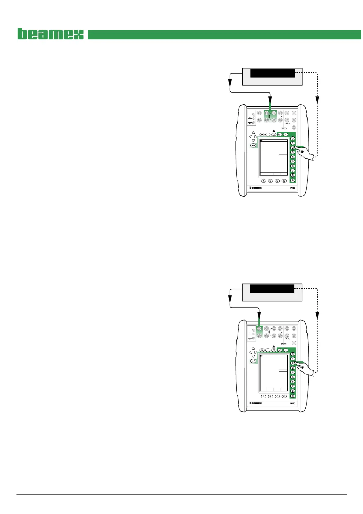
Adjusting the Resistance Measurement in ET Module (0 … 4000 ohm)
Quantity: Resistance
Function/Port: ET: Resistance Meas.
Use precision resistors and connect them to the cali-
brator’s terminals highlighted in the adjacent picture. In
case the accuracy of the resistors are not good enough,
check the correct resistance using an accurate Digital
Multimeter. Also read the note below the picture.
Adjustment point ranges, ohm
1: 60 … 87
2: 120 … 175
3: 240 … 350
4: 700 … 1025
5: 1400 … 2050
6: 2800 … 4100
Select a precision resistor that is inside the limits of the
first adjustment point range. Enter the correct resistance
seen on the Digital Multimeter’s display to Span Refer-
ence Value field in the calibrator. Continue through all
the adjustment points
When all adjustment points are checked, select either
another Quantity and Function/Port combination or save
the adjustment result as described in chapter Saving
Adjustment Data on page 16.
MENU
Calibration
Mode
Precision Resistor
W
70.0000
17.10.2002 10:26
Resistace
ET: Resistance Meas.
W69.998
Span Reference Value 70.00012
MULTIFUNCTION CALIBRATOR
T/C, Low V
4-w meas
R, RTD
3 & 4-w meas
V, I,
+24V
I
meas/sink
Low V
HART
®
T/C INT. RJ
T/C OR EXT
WIRES ONLY
2-w xmtr
V, ,
?
MEASURE
OUTPUTSENSOR MEASURE & SIMULATE
ET E
Max input:
60 VDC/30 VAC
Note.
Do not connect both the calibrator and the
Digital Multimeter to the resistor simultane-
ously. The resistance measurement currents
of the calibrator and the Digital Multimeter
disturb each other resulting in unreliable
measurements.
Adjusting the Low Voltage Measurement in ET Module (±500 mV)
Quantity: Voltage
Function/Port: ET: Low V. Sensor Mea
Use an accurate millivolt source and connect to the cali-
brator’s terminals highlighted in the adjacent picture. In
case the accuracy of the millivolt source is not good
enough, check the correct voltage using an accurate
Digital Multimeter.
Adjustment point ranges, mV
1: 90 … 125
2: 150 … 250
3: 400 … 500
Generate a voltage that is inside the limits of the first
adjustment point range. Enter the correct voltage seen
on the Digital Multimeter’s display to Span Reference
Value field in the calibrator. Continue through all the ad-
justment points
When all adjustment points are checked, select either
another Quantity and Function/Port combination or save
the adjustment result as described in chapter Saving
Adjustment Data on page 16.
Source/DMM
mV
499.97357
17.10.2002 9:42
Voltage
ET: Low V. Sensor Meas.
mV499.97
Span Reference Value 499.97357
Field MENU
Calibration
Mode
MULTIFUNCTION CALIBRATOR
T/C, Low V
4-w meas
R, RTD
3 & 4-w meas
V, I,
+24V
I
meas/sink
Low V
HART
®
T/C INT. RJ
T/C OR EXT
WIRES ONLY
2-w xmtr
V, ,
?
MEASUREOUTPUTSENSOR MEASURE & SIMULATE
ET E
Max input:
60 VDC/30 VAC