Calibration and Adjustment Instructions for MC5 Multifunction Calibrator For Main Firmware Version 1.90
Page 14/16
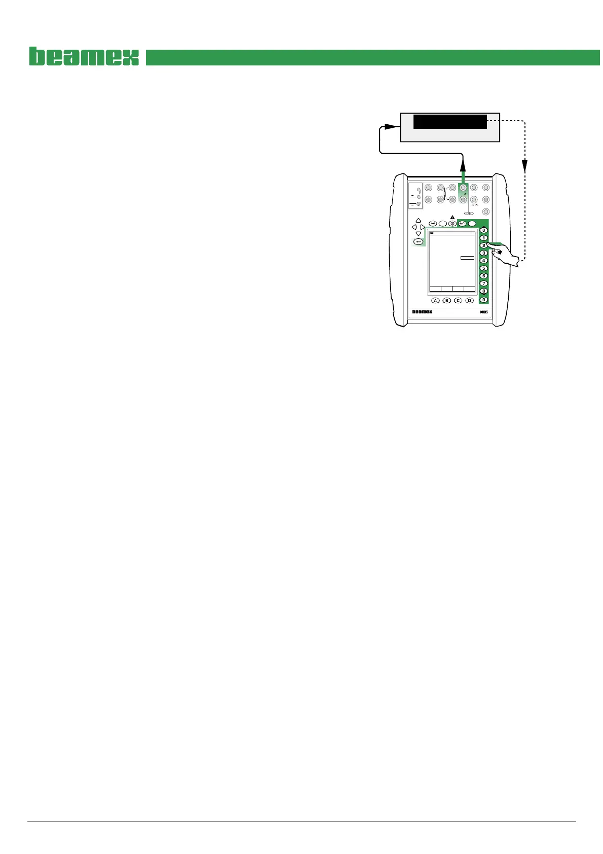
Adjusting the Voltage Generation in ET Module (±12 V)
Quantity: Voltage
Function/Port: ET: Voltage Generation
The lowermost measurement value in the voltage gen-
eration window is the calibrator’s own feedback meas-
urement of the generated voltage. It is accurate enough
for trimming the generated value. The Digital Multimeter
connected to the loop is optional.
Generation adjustment point ranges, V
Low: 0
High: 10 … 12
Feedback measurement adjustment point ranges, V
1: 2.4 … 2.9
2: 4.9 … 5.8
3: 10 … 12
Move the field indicator to the uppermost field and enter
zero as the low adjustment point. Enter the voltage seen
on the Digital Multimeter’s display to Span Reference
Value field in the calibrator. Then generate a voltage that
is inside the high adjustment point range and enter the
correct value for that point too. Repeat the low and high
adjustments until the voltage generation is accurate
enough.
DMM
V
11.000871
17.10.2002 9:53
Voltage
ET: Voltage Generation
V11.000
Measurement V
Span Reference Value 11.001
11.001
Field MENU
Calibration
Mode
MULTIFUNCTION CALIBRATOR
T/C, Low V
4-w meas
R, RTD
3 & 4-w meas
V, I,
+24V
I
meas/sink
Low V
HART
®
T/C INT. RJ
T/C OR EXT
WIRES ONLY
2-w xmtr
V, ,
?
MEASURE
OUTPUTSENSOR MEASURE & SIMULATE
ET E
Max input:
60 VDC/30 VAC
The feedback measurement need also be adjusted. To adjust it, move the field indicator to the
uppermost field and enter a value within the first feedback measurement adjustment range. En-
ter the voltage seen on the Digital Multimeter’s display to Span Reference Value field in the cali-
brator. Continue through all the adjustment points.
When ready, select either another Quantity and Function/Port combination or save the adjust-
ment result as described in chapter Saving Adjustment Data on page 16.
Notes.
For feedback measurement adjustment point ranges 1 and 2, only the lowermost value in the voltage generation win-
dow (the feedback measurement value) is changed.
The feedback measurement adjustment point range 3 is both for the voltage generation range and the feedback meas-
urement adjustment. Thus both values are updated.