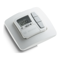
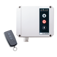
The BECK-O-TRONIC 4, Centronic version, is a high-quality door control unit designed for the operation of tubular drives in roller doors with fixed limit stops or a barrel cover, compliant with EN 12453. It features a radio receiver compatible with the Centronic range of control units, excluding those with time switching or sun protection functions. For downward travel in maintained operation, a closing edge safety device is required. This control unit is not suitable for use in potentially explosive areas.
Function Description:
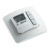
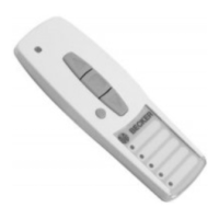
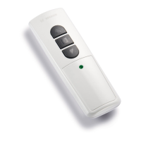
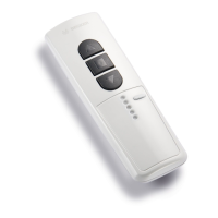
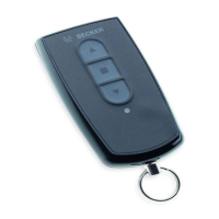
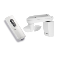
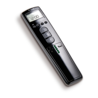
The BECK-O-TRONIC 4 offers simple and convenient connection, ease of handling, and high flexibility. It includes automatic limit position detection and defined buttons for UP, STOP, and DOWN operations, available on both the control unit and the hand-held transmitter. The modular system allows for plug-in radio and sensors, and the clear display provides operating status and error messages. An optical safety edge can be connected without an external sensor.
The control unit supports various operating modes configurable via 8 DIP switches:
- Setting Mode: Limit position detection and running time monitoring are off, allowing for live adjustment of the door system's limit positions. This mode is only suitable for tubular drives with mechanical limit switching. Once settings are complete, DIP switch 1 must be set to OFF (door mode). Operating the door in setting mode is not permitted.
- Door Mode: The control unit is ready for operation, with limit position detection and running time monitoring active.
- Dead-man Mode: The door can only be controlled via a hard-wired device. The DOWN button must be held down continuously for downward travel. Upward travel is in maintained operation. The hand-held transmitter can only be used for upward travel.
- Closing Edge Stop Mode: During closing, if a light barrier or safety edge is activated, the door stops. No function in the UP direction. After an obstruction, the door must first clear it before lowering again.
- Closing Edge Reverse Travel Mode (clearing an obstruction): During closing, if a light barrier or safety edge is activated, the door stops and reverses. No function in the UP direction.
- Closing Edge Reopening Travel Mode: During closing, if a light barrier or safety edge is activated, the door stops and travels to the upper limit position. No function in the UP direction.
The unit also supports various outdoor light and advance warning light functions:
- Outdoor Light Mode: Light switches on for 2 minutes with every door movement and can be activated via the stop or radio light button (with a 4-channel hand-held transmitter).
- Automatic Staircase Lighting: Triggers a connected staircase light for 2 seconds with every door movement. Can also be activated via the stop or remote light button.
- General Advance Warning: Provides a 3-second warning before every door movement. The warning light switches off only after a limit position is reached.
- Advance Warning for Automatic Closing: Provides a 3-second warning before every automatic closure. The warning light switches off only after a limit position is reached.
- Type of Warning Light: Automatic Flashing Warning Light: For devices like a rotating beacon.
- Type of Warning Light: Pulsed Warning Light: Output is pulsed at 1 Hz for a flashing effect, as the warning light does not flash automatically.
Automatic closing features include:
- Automatic Closing Deactivated.
- Automatic Closing without Light Barrier Reduction: Door closes after a 1-minute delay. Aborted after 5 unsuccessful attempts if an obstruction is encountered. Door must be moved to the lower limit position manually or via a hard-wired device.
- Automatic Closing with Light Barrier Reduction to 3 Seconds: Door closes after a 1-minute delay, reduced to 3 seconds by passing the light barrier. Aborted after 5 unsuccessful attempts if an obstruction is encountered.
- Automatic Closing with Light Barrier Reduction to 15 Seconds: Door closes after a 1-minute delay, reduced to 15 seconds by passing the light barrier. Aborted after 5 unsuccessful attempts if an obstruction is encountered.
The control unit supports various safety edge sensors:
- Safety Edge with 1k2 Ohm Terminating Resistor (without testing): Standard operation.
- Safety Edge with 1k2 Ohm Terminating Resistor (with testing): Safety edge is tested during every closing movement; it must be activated within 2 seconds of the pre-limit switch activation (positive testing).
- Safety Edge with 8k2 Ohm Terminating Resistor (without testing): Standard operation.
- Safety Edge with 8k2 Ohm Terminating Resistor (with testing): Safety edge is tested during every closing movement; it must be activated within 6 seconds of the pre-limit switch activation (positive testing).
- Optical Edge from Fraba: Support for optical safety edges.
Important Technical Specifications:
- Dimensions (W x H x D): 155 x 130 x 50 mm
- Housing Material: PC
- Degree of Protection: IP54, for indoor installation only
- Supply Voltage: 230 V / 50 Hz (connection type Y)
- Input Power: 6 VA
- Fuse: 2 A slow-blow
- Drive Switching Capacity: 1 drive 230 V / 50 Hz, maximum 260 VA
- Light Switching Capacity: 230 V / 50 Hz, maximum 100 W
- Control Voltage: 24 V, maximum 100 mA
- Temperature Range: -10°C to +50°C
- Radio Frequency: 868.3 MHz
- Service Life: Designed for 100,000 operating cycles.
Usage Features:
- Programming:
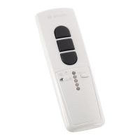
- Master Transmitter: Press the programming button (B) on the radio receiver for 3 seconds. The LED (D) flashes, indicating programming mode for 3 minutes. Then, press the programming button (C) on the transmitter for 3 seconds. The transmitter's LED lights up for 3 seconds, and the receiver's LED (D) goes out, confirming completion.
- Additional Transmitters: Up to 7 additional transmitters can be programmed. Press the programming button (C) of the master transmitter for 3 seconds (LED (D) lights once). Then, press the programming button of the new transmitter for 3 seconds (LED (D) lights once). Press the new transmitter's programming button again for 3 seconds (LED (D) lights twice), confirming programming.
- Deleting Transmitters:
- Individual Transmitters: Press the programming button (C) on the master transmitter for 3 seconds (LED (D) lights once). Press the programming button of the transmitter to be deleted for 3 seconds (LED (D) lights once). Press it again for 10 seconds (LED (D) lights twice), confirming deletion. The master transmitter cannot be deleted, only overwritten.
- All Transmitters (except master): Press the programming button (C) on the master transmitter for 3 seconds (LED (D) lights once). Press it again for 3 seconds (LED (D) lights once). Press it a third time for 10 seconds (LED (D) lights twice), confirming deletion of all other transmitters.
- Overwriting Master Transmitter: Press the programming button (B) on the radio receiver for 3 seconds (LED (D) flashes, programming mode for 3 minutes). Press the programming button of the new master transmitter for 10 seconds (LED (D) goes out), confirming the new master transmitter is programmed and the old one overwritten.
- Installation: Open the control unit cover, unplug and remove the keyboard overlay. Remove required cut-outs in the housing bottom. Use the provided drilling template to mount the housing.
- Wiring: Connect the motor, outdoor light/advance warning light, light barrier, external key-operated push-button, and bottom rail sensor as per the connecting diagram. Ensure electrical work is performed by qualified personnel, disconnecting mains power before connecting equipment. Pull insert sleeves over cables before pushing them into the housing.
Maintenance Features:
- The control unit is maintenance-free.
- Cleaning: Only clean the outside of the housing with a suitable cloth. Do not use cleaning agents that may damage the plastic.