PROFIBUS
BC3150 85Version: 2.1.0
PROFIBUS wire colors
PROFIBUS line M12 D sub
B red Pin 4 Pin 3
A green Pin 2 Pin 8
RS485 - Fundamental properties
RS-485 transmission according to the PROFIBUS standard
Network topology Linear bus, active bus terminator at both ends, stubs are possible.
Medium Screened twisted cable, shielding may be omitted, depending upon the
environmental conditions (EMC).
Number of stations 32 stations in each segment with no repeater. Can be extended to
127stations with repeater
Max. bus length without
repeater
100m at 12Mbit/s
200m at 1500kbit/s, up to 1.2km at 93.75kbit/s
Max. bus length with repeater Line amplifiers (repeaters) can increase the bus length to the order of
10km. The number of repeaters possible is at least 3, and, depending on
the manufacturer, may be up to 10
Data transfer rate 9.6, 19.2, 93.75, 187.5, 500, 1500kbit/s, up to 12Mbit/s, infinitely variable
Connector 9-pin D sub connector for IP20
M12 round connector for IP65/67
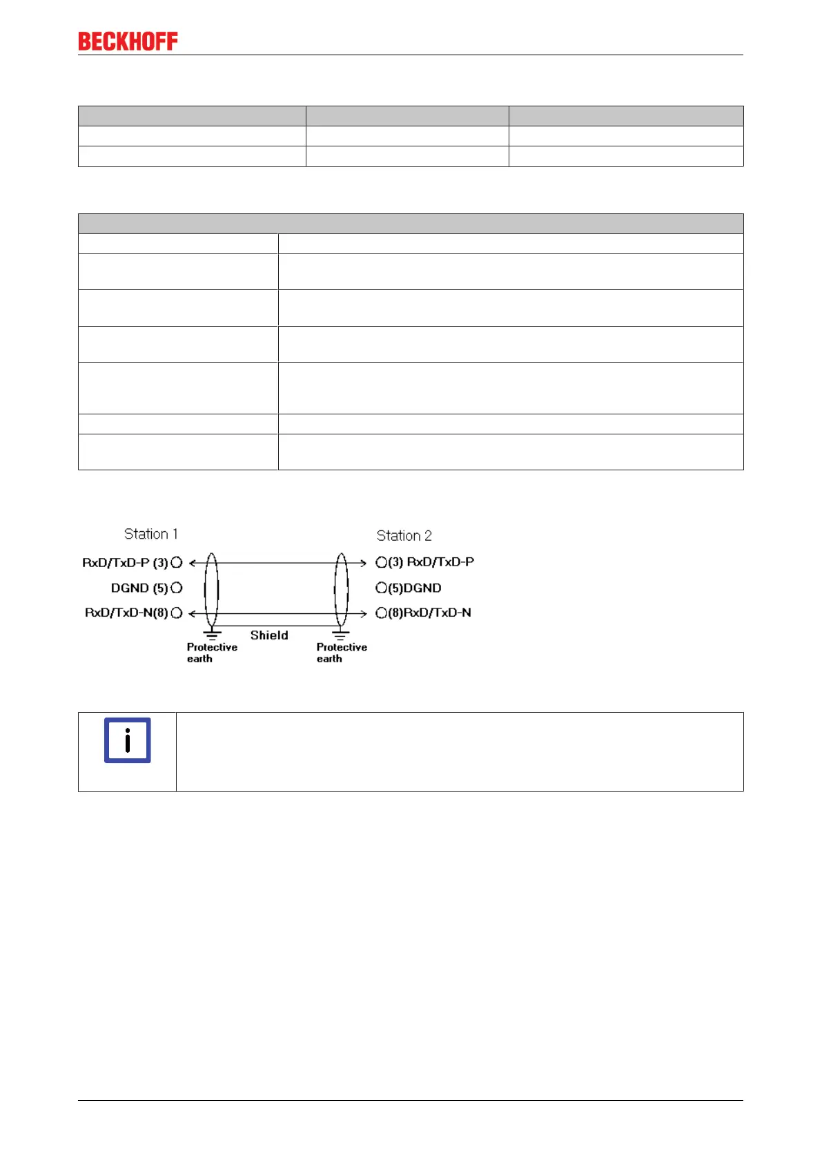
Cabling for PROFIBUS-DP and PROFIBUS_FMS
Fig.75: PROFIBUS cable assignment
Note
Termination resistors
In systems with more than two stations all devices are wired in parallel. The PROFIBUS ca-
ble must be terminated with resistances at both ends, in order to avoid reflections and as-
sociated transfer problems.
Addressing
Setting of station addresses
The PROFIBUS address must be set using the two rotary selection switches behind the transparent cover.
The default setting is 11. Any address is permitted, but each address may only be used once within the
network. The address can be modified when the Fieldbus Box (Bus Coupler) is switched off. Release the
cover (Fieldbus Box only) and set the switches to the required position using a screwdriver. Make sure that
the switches engage properly. The change in address is active as soon as the device is switched on.
Fieldbus Box address
The switch on the left represents the tens, while that on the right represents the units.