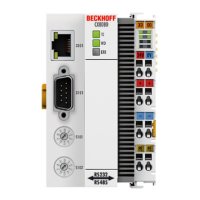
RS232 - Interface
BC8050 und BC815066 Version: 3.0.0
the terminal composition or the cycle times, and the programmed configuration can be written. It is also
possible for a manual K-bus reset to be carried out. The 2-byte PLC interface requires two bytes each of
input and output data. They are handled using a special protocol. A description of the 2 byte PLC interface,
the registers available in the Bus Couplers and of function blocks for various PLC systems that support the 2
byte PLC interface can be supplied on request.
* not implemented on the BC8150
2 byte diagnostic interface
The terminals' error messages can be sent over the 2-byte diagnostic interface. K-bus diagnostics must
however be activated for this purpose. The 2-byte diagnostic interface occupies two bytes each of input and
output data. A special protocol is processed via these two bytes. A description of the 2 byte-diagnostic
interface can be supplied on request.
6.1.1.4 Modbus error response
When the user sends the slave either a request or information that the coupler does not understand, the
slave responds with an error report. This answer contains the function and the error code. 0x80 is added to
the value returned by the function.
Code Name Meaning
1 ILLEGAL FUNCTION Modbus function not implemented
2 ILLEGAL DATA ADDRESS Invalid address or length
3 ILLEGAL DATA VALUE Invalid parameters
- Diagnostics functions
- Wrong register
4 SLAVE DEVICE ERROR Watchdog or K-bus error
6.1.1.5 Functions
6.1.1.5.1 Modbus functions in the BC8150
In the Modbus protocol, the functions determine whether data is to be read or written, and what kind of data
is involved.
Function Code Description
Read holding register [}66]
3 Read analog outputs and inputs / GPR
Read input register [}68]
4 Read analog inputs / GPR
Preset single register [}69]
6 Write one analog output / GPR
Diagnosis [}70]
8 Diagnosis
Preset multiple register [}72]
16 Write a number of analog outputs / GPRs
Read / write registers [}73]
23 Write and read a number of process data outputs / GPRs
GPR (General Preset Register) - register structure of the Modbus interface (see Appendix)
6.1.1.5.2 Function 3: READ HOLDING REGISTERS
The READ HOLDING REGISTERS function can be used to read the input and output words and the
registers. The inputs have offsets 0 - 0xFF while the outputs have offsets 0x800 - 0x8FF.
The first two analog outputs are read in this example. The analog outputs begin at offset 0x800 (hex). The
length indicates the number of channels to be read.
 Loading...
