Operation
EL1918 and EL1918-2200 37Version: 2.0.0
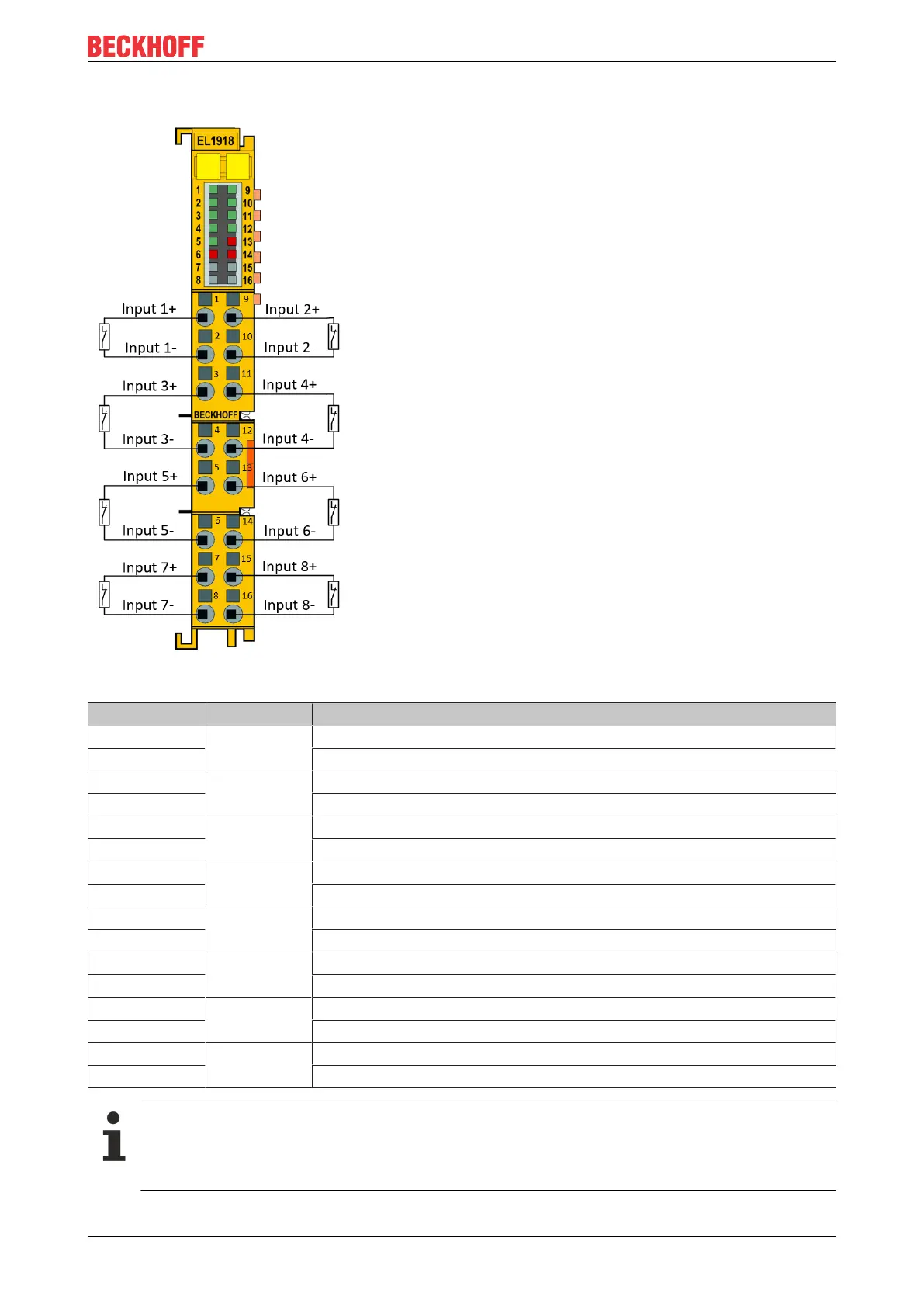
5.2.4.4 Connection
Fig.15: EL1918 connection
Terminal point Input Signal
1 1 Input 1+ (clock output)
2 Input 1- (safe input)
3 3 Input 3+ (clock output)
4 Input 3- (safe input)
5 5 Input 5+ (clock output)
6 Input 5- (safe input)
7 7 Input 7+ (clock output)
8 Input 7- (safe input)
9 2 Input 2+ (clock output)
10 Input 2- (safe input)
11 4 Input 4+ (clock output)
12 Input 4- (safe input)
13 6 Input 6+ (clock output)
14 Input 6- (safe input)
15 8 Input 8+ (clock output)
16 Input 8- (safe input)
Configurable inputs
The inputs 1 to 8 can be occupied as you want with normally closed contacts or normally open
contacts. The corresponding analysis is carried out in the safety PLC. The input labeled Input x- is
used for connecting OSSD sensors (self-testing sensors).