Operation
EL1918 and EL1918-220044 Version: 2.0.0
Index Name Default value/
unit
Description
80x0:04 Diag TestPulse active TRUE / Boolean Activation of test pulses for the
corresponding input module
80x0:05 Module Fault Link active TRUE / Boolean If a module error occurs in this module, a
module error is also set for all other
modules of this TwinSAFE component for
which this parameter is also set to TRUE.
80x1:01 InputFilterTime 0x000A / 0.1ms Input filter of the safe input. Following this
time the internal input signal changes to
the applied signal state.
80x1:02 DiagTestPulseFilterTime 0x0002 / 0.1ms Input filter for the test pulse signal
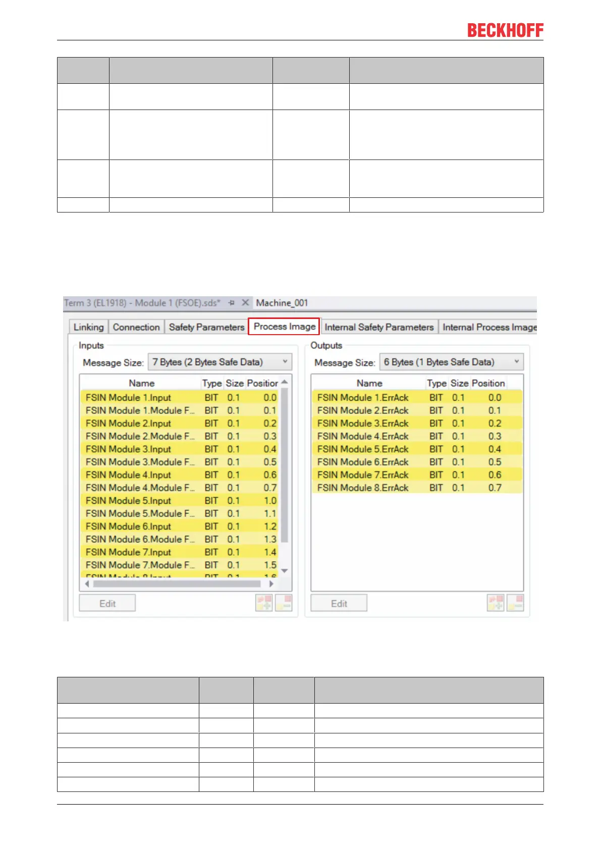
5.3.7 Process image of the EL1918
The process image of the EL1918 consists of 7 bytes process data in the input and 6 bytes process data in
the output.
Fig.25: Process image of the EL1918
The assignment of the individual signals in the safe data is listed in the following table.
Name Process
image
Bit position Description
FSIN Module1.Input IN 0.0 Safe input 1
FSIN Module1.Module Fault IN 0.1 Module error information for input 1
FSIN Module2.Input IN 0.2 Safe input 2
FSIN Module2.Module Fault IN 0.3 Module error information for input 2
FSIN Module3.Input IN 0.4 Safe input 3
FSIN Module3.Module Fault IN 0.5 Module error information for input 3