Operation
EL1918 and EL1918-220046 Version: 2.0.0
NOTE
Execution time of the logic function
The execution time of the logic program - with identical logic program - will typically be longer compared to
the EL6910, since the safe I/O signals must be processed additionally. This also has a corresponding effect
on the processing of the I/O signals, since with increasing project size these can only be evaluated with a
lower frequency.
Process image size max. 1486byte per data direction
(maximum memory size 0x1E00 for 3 buffers, ie with the same size of
input and output process data, a maximum size of 1280 bytes per data
direction is possible. Only straight start addresses are possible, so fill
bytes must be taken into account)
TwinSAFE connections 128 max.
(up to 255 CRCs in total; 1 CRC is required for a TwinSAFE connection
with 1 or 2 byte safe data.)
Safe data per TwinSAFE
connection
maximum 126byte (telegram length 255byte)
TwinSAFE blocks maximum 512 (when using ESTOP function blocks with complete input
and output mapping, other function blocks can lead to a smaller
maximum number)
TwinSAFE groups 128 max.
TwinSAFE user 40 max.
Standard PLC inputs dynamic (memory-dependent), max. 1484byte
Standard PLC outputs dynamic (memory-dependent), max. 1484byte
NOTE
Project development
TwinCAT 3.1 Build 4022.25 or newer is required to use the internal logic functions. If the EL1918 is used as
TwinSAFE slave with the default project, at least an EL6910, EK1960 or newer logic component is required
as TwinSAFE master.
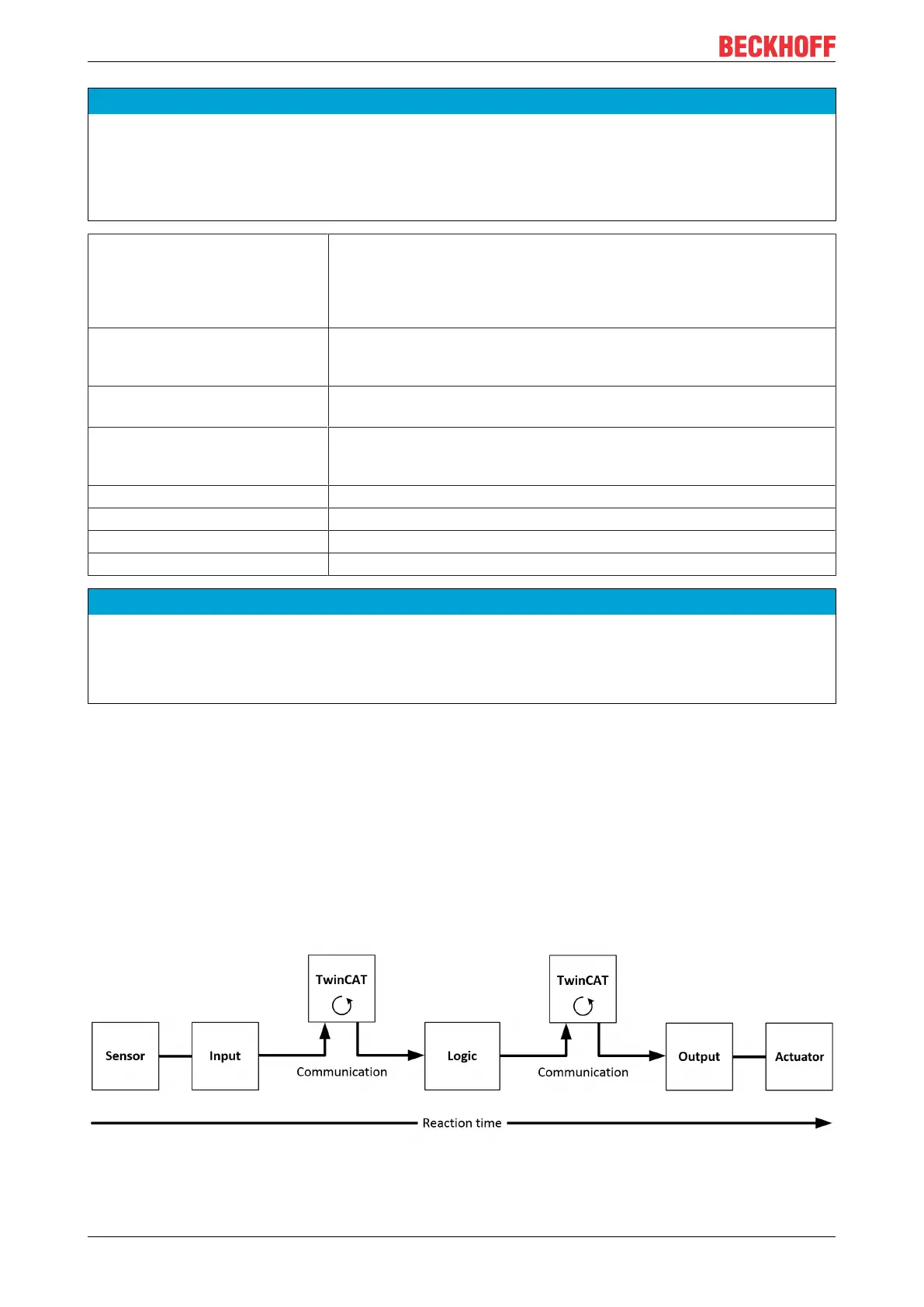
5.4 TwinSAFE reaction times
The TwinSAFE terminals form a modular safety system that exchanges safety-oriented data via the Safety-
over-EtherCAT protocol. This chapter is intended to help you determine the system's reaction time from the
change of signal at the sensor to the reaction at the actuator.
Typical reaction time
The typical reaction time is the time that is required to transmit information from the sensor to the actuator, if
the overall system is working without error in normal operation.
Fig.27: Typical reaction time