Commissioning
EL500x 141Version: 3.6
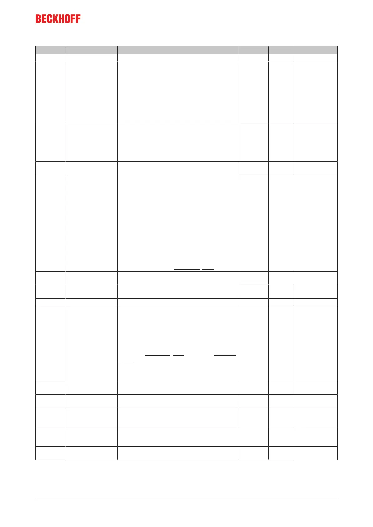
Index 1C33 SM input parameter
Index (hex) Name Meaning Data type Flags Default
1C33:0 SM input parameter Synchronization parameters for the inputs UINT8 RO 0x20 (32
dec
)
1C33:01 Sync mode Current synchronization mode:
• 0: Free Run
• 1: Synchron with SM 3 Event (no outputs
available)
• 2: DC - Synchron with SYNC0 Event
• 3: DC - Synchron with SYNC1 Event
• 34: Synchron with SM 2 Event (outputs
available)
UINT16 RW 0x0022 (34
dec
)
1C33:02 Cycle time Cycle time (in ns):
• Free Run: Cycle time of the local timer
• Synchronous with SM 2 event: Master cycle
time
• DC mode: SYNC0/SYNC1 Cycle Time
UINT32 RW 0x000F4240
(1000000
dec
)
1C33:03 Shift time Time between SYNC0 event and reading of the in-
puts (in ns, only DC mode)
UINT32 RO 0x00000000 (0
dec
)
1C33:04 Sync modes sup-
ported
Supported synchronization modes:
• Bit 0: free run is supported
• Bit 1: Synchronous with SM 2 Event is
supported (outputs available)
• Bit 1: Synchronous with SM 3 Event is
supported (no outputs available)
• Bit 2-3 = 01: DC mode is supported
• Bit 4-5 = 01: input shift through local event
(outputs available)
• Bit 4-5 = 10: input shift with SYNC1 event (no
outputs available)
• Bit 14 = 1: dynamic times (measurement
through writing of 0x1C33:08 [}141])
UINT16 RO 0xC007 (49159
dec
)
1C33:05 Minimum cycle time Minimum cycle time (in ns) UINT32 RO 0x0000FDE8
(65000
dec
)
1C33:06 Calc and copy time Time between reading of the inputs and availability of
the inputs for the master (in ns, only DC mode)
UINT32 RO 0x00000000 (0
dec
)
1C33:07 Minimum delay time - UINT32 RO 0x00000000 (0
dec
)
1C33:08 Command With this entry the real required process data provi-
sion time can be measured.
• 0: Measurement of the local cycle time is
stopped
• 1: Measurement of the local cycle time is
started
The entries 0x1C33:03 [}141], 0x1C33:06, 0x1C33:09
[}141] are updated with the maximum measured val-
ues.
For a subsequent measurement the measured val-
ues are reset
UINT16 RW 0x0000 (0
dec
)
1C33:09 Maximum Delay time Time between SYNC1 event and reading of the in-
puts (in ns, only DC mode)
UINT32 RO 0x00000000 (0
dec
)
1C33:0B SM event missed
counter
Number of missed SM events in OPERATIONAL (DC
mode only)
UINT16 RO 0x0000 (0
dec
)
1C33:0C Cycle exceeded
counter
Number of occasions the cycle time was exceeded in
OPERATIONAL (cycle was not completed in time or
the next cycle began too early)
UINT16 RO 0x0000 (0
dec
)
1C33:0D Shift too short counter Number of occasions that the interval between
SYNC0 and SYNC1 event was too short (DC mode
only)
UINT16 RO 0x0000 (0
dec
)
1C33:20 Sync error The synchronization was not correct in the last cycle
(outputs were output too late; DC mode only)
BOOLEAN RO 0x00 (0
dec
)
 Loading...