Product overview
KL6031/KS6031, KL6041/KS604110 Version: 2.1.0
2.3 KL6031 – Basic function principles
The KL6031 serial interface terminal enables the connection of devices with an RS232 interface (e.g. bar
code scanners). Data can be exchanged with the controller in full duplex mode, independent of the higher-
level bus system. The receive buffer has 1024bytes, the transmit buffer 16bytes. The data transfer between
terminal and controller is handled via a handshake in the status and control byte. The factory setting of the
terminal is 9600bit, 8databits, 1stopbit, no parity, RTS/CTS control active.
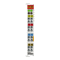
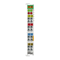
LED display
The Run LED indicates the operating state of the terminal.
• On – normal operation
• Off – Watchdog timer overflow has occurred. If no process data is transmitted from the Bus Coupler for
100ms, the green LED goes out.
The TxD and RxD LEDs indicate the states of the signal lines.
Process data - alternative output format
In the alternative output format, 4 or 5bytes (3bytes for data and 1 or 2 control/status byte(s)) are mapped
in the Bus Coupler. The KL6031 is delivered in the alternative format. The mapping of the terminal in the
alternative format is described in more detail in the chapter "Terminal configuration".
Process data - standard output format
In the standard output format, 4 bytes of user data (3 bytes of user data and 1 Control/Status byte) are
mapped by default in the Bus Coupler. By changing the parameters of the KL6031, up to 5bytes of user data
can be transferred.
Reference
The chapter "Access from the user program" provides an overview of the possible mapping configurations
[}41] depending on the adjustable parameters.