Product overview
KL6031/KS6031, KL6041/KS604112 Version: 2.1.0
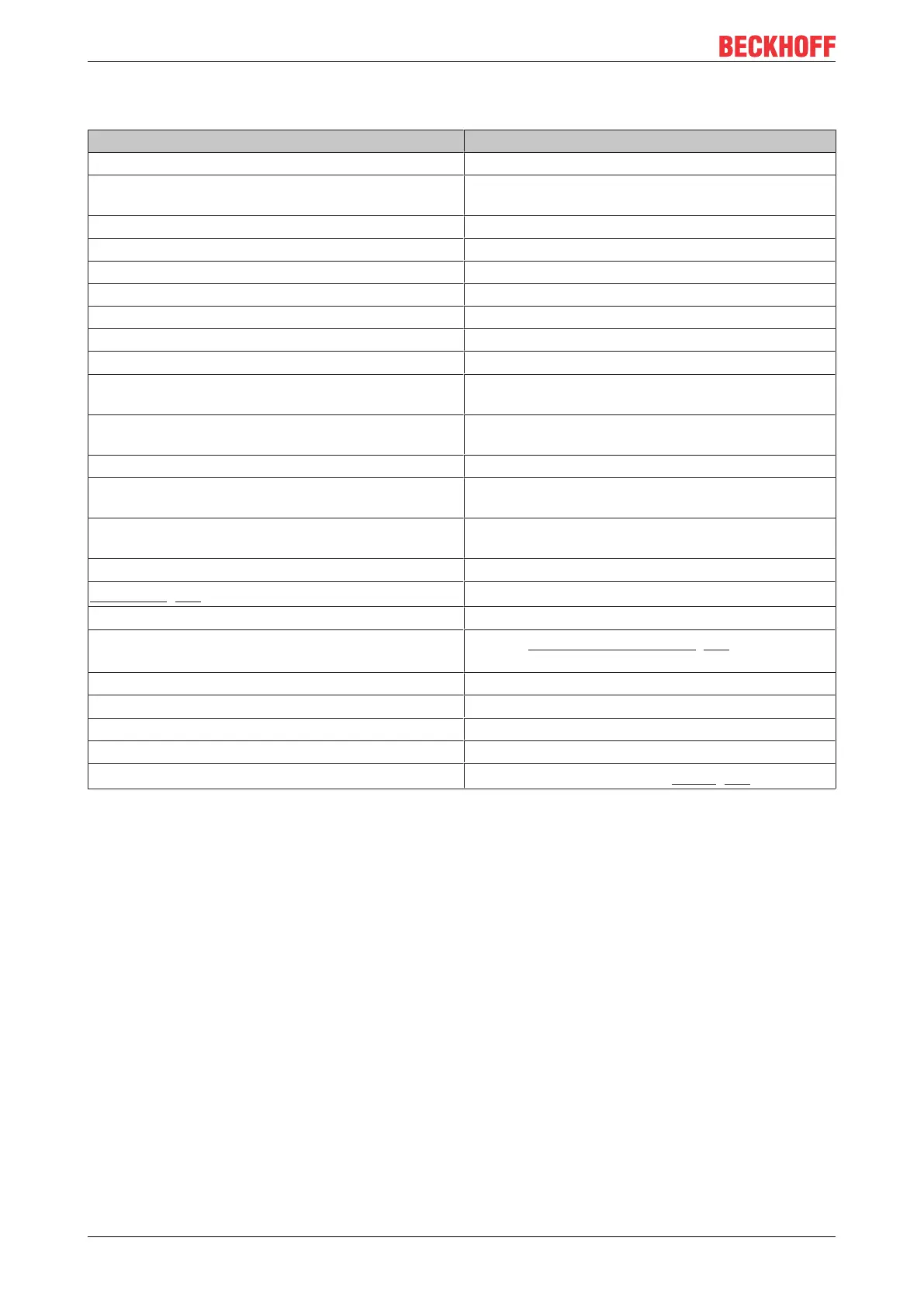
2.5 KL6041 - Technical data
Technical data KL6041, KS6041
Data transfer channels TxD and RxD, full/half duplex
Data transfer rate 9600bit/s, 8data bits, no parity and one stop bit are
pre-set (max. 115200bit/s)
Bit transfer with differential signal
Line impedance 120Ω
Transmission link approx. 1000m twisted-pair
Power supply via the K-bus
Current consumption from K-bus typ. 65mA
Electrical isolation 500V (K-bus/signal voltage)
Data buffer 1024 byte receive buffer, 128 byte transmit buffer
Bit width in process image input/output: 22 x 8 bit user data, 2 x 8 bit control/
status (up to 22 bytes of user data possible)
Configuration no address setting, configuration via bus coupler or
controller
Weight approx.50g
Permissible ambient temperature range during
operation
25°C ... +60°C (extended temperature range)
Permissible ambient temperature range during
storage
-45 °C ... +85 °C
Permissible relative humidity 95% no condensation
Mounting [}15]
on 35mm mounting rail according to EN60715
Pluggable wiring for all KSxxxx terminals
Enhanced mechanical load capacity
yes, see Installation instructions [}17] for enhanced
mechanical load capacity
Vibration/ shock resistance conforms to EN60068-2-6/ EN60068-2-27
EMC immunity/ emission conforms to EN61000-6-2/ EN61000-6-4
Protection class IP20
Installation position variable
Approvals/markings*
CE, UKCA, cULus, EAC, GK, ATEX [}22]
2.6 KL6041 – Basic function principles
The KL6041 serial interface terminal enables the connection either
• of devices with an RS485 interface or
• of a device with an RS422 interface (peer to peer).
Depending on the higher-level fieldbus system, data can be exchanged with the controller in full-duplex or
half-duplex mode. The size of the receive buffer is 1024bytes, that of the transmit buffer 128bytes. The data
transfer between terminal and controller is handled via a handshake in the status and control byte. The
factory setting of the terminal is 9600bit, 8databits, 1stopbit, no parity, full duplex mode.
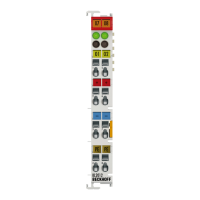
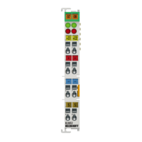
LED display
The Run LED indicates the operating state of the terminal.
On – normal operation
Off – Watchdog timer overflow has occurred. If no process data is transmitted from the Bus Coupler for
100ms, the green LED goes out.
The TxD and RxD LEDs indicate the states of the signal lines.