Access from the user program
KL6031/KS6031, KL6041/KS604134 Version: 2.1.0
5 Access from the user program
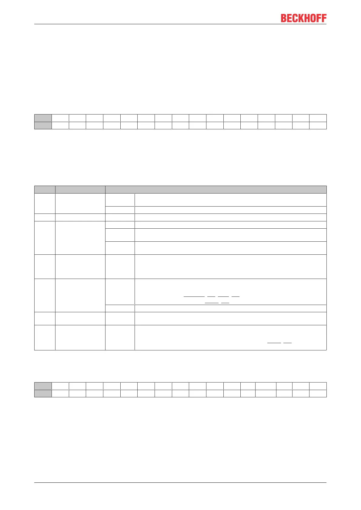
5.1 Control and status word
Control word
The control word (CW) is located in the output process image, and is transmitted from the controller to the
terminal.
Bit CW.15 CW.14 CW.13 CW.12 CW.11 CW.10 CW.9 CW.8 CW.7 CW.6 CW.5 CW.4 CW.3 CW.2 CW.1 CW.0
Name OL7 OL6 OL5 OL4 OL3 OL2 OL1 OL0 - OL2* OL1* OL0* SC IR RA TR
Bits CW.15 to CW.8 are only shown if the large process image is used.
If the small or medium process image is used, only bits CW.7 to CW.0 are shown as control bytes! The
number of output bytes available for transfer from the controller to the terminal is displayed by bits
OL2*...OL0*.
Key
Bit Name Description
CW.15
...
CW8
OL7...OL0
(OutLenght)
1
dec
... 22
dec
If the large process image is used: Number of output bytes () available for transfer from
the controller to the terminal.
- If the small/medium process image is used: not shown
CW.7 - 0
bin
reserved
CW.6
…
CW.4
OL2*...OL0*
(OutLenght*)
0 If the large process image is used: reserved
1...6 If the medium process image is used: Number of output bytes available for transfer from
the controller to the terminal.
1...4 If the small process image is used: Number of output bytes available for transfer from
the controller to the terminal.
CW.3 SC
(SendContinious)
rise Continuous sending of data from the FIFO.
The send buffer is filled (up to 128bytes) by the controller. The buffer content is sent
with rising edge of bit SC. The terminal acknowledges the data transfer to the controller
through setting of bit SW.2. SW.2 is cancelled with CW.3.
CW.2 IR
(InitRequest)
1
bin
The controller requests terminal for initialization. The send and receive functions are
blocked, the FIFO pointers are reset and the interface is initialized with the values from
the relevant registers (R32-R35 [}39], R18 [}39]). The terminal acknowledges com-
pletion of the initialization via bit SW.2 [}34] (IA).
0
bin
The controller once again requests the terminal to prepare for serial data exchange.
CW.1 RA
(ReceiveAccepted)
toggle The controller acknowledges receipt of data by changing the state of this bit. Only then
new data can be transferred from the terminal to the controller.
CW.0 TR
(TransmitRequest)
toggle Via a change of state of this bit the controller notifies the terminal that the DataOut bytes
contain the number of bytes indicated via the OL bits. The terminal acknowledges re-
ceipt of the data in the status byte via a change of state of bit SW.0 [}34] (TA). Only
now new data can be transferred from the controller to the terminal.
Status word
The status word (SW) is located in the input process image, and is transmitted from terminal to the controller.
Bit SW.15 SW.14 SW.13 SW.12 SW.11 SW.10 SW.9 SW.8 SW.7 SW.6 SW.5 SW.4 SW.3 SW.2 SW.1 SW.0
Name IL7 IL6 IL5 IL4 IL3 IL2 IL1 IL0 - IL2* IL1* IL0* BUF_F IA RR TA
Bits SW.15 to SW.8 are only shown if the large process image is used.
If the small or medium process image is used, only bits SW.7 to SW.0 are shown as status bytes! The
number of input bytes available for transfer from the terminal to the controller is displayed by bits IL2*...IL0*.