GB Sound module USM-RC-3
18 BEIER-Electronic 11.10.2021
Unfortunately, a fuse can never always protect all wrong connections 100%!
Therefore, please make sure that everything is connected correctly.
As a further option you can also connect a switch into the power supply of the sound
module to switch it off. It is a method which has the advantage of less power
consumption if permanently no sound is needed. But the switching-outputs and
servo-outputs are also disabled if switched off!
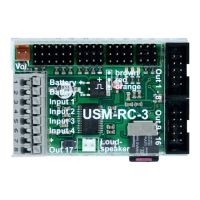
Connection of loudspeaker
The loudspeaker ist connected to X7 at the USM-RC-3.
The red cable is connected to the positive and the black to the negative pole of the
loudspeaker.
The supplied loudspeaker connection cables should not be extended to prevent
interference of the receiver (especially with FM systems)! The loudspeaker cable
should be installed with a maximum of distance to receiver and antenna.
Information about power supply of receiver:
The voltage at the terminals X1/1 and X1/2 powers the audio amplifier for the sound
playback, the switching outputs and the rest of the internal electronic of the sound
module.
The receiver is not powered with this voltage. It does not matter, if e.g. a voltage is
connected to X2 over a BEC or a receiver battery.
A BEC voltage from the speed controller is directly connected to the receiver over
the terminals of X2. Connected servos to X5 / 1 - X5 / 4 are also supplied via the
BEC voltage.
Therefore you can plan your receiver's power supply just as if you connect no sound
module. For example for 2 speed controllers with BEC, one BEC must be disabled.
Connection of switching-outputs 1 - 16
The outputs 1 - 16 of the module are located at the pin connectors X3 and X4.
The supplied ribbon cable can be used to connect the outputs. For easier
connection, the terminals AKL-8 and AKL-8-W can be ordered from our shop.
Of course other cables/plugs with a cross section of 0,14 mm² - 0,5 mm² can be
connected as well.
The USM-RC-3 is always switching the negative pole to each output and thus to the
connected load. The negative pole is always connected to the load (see wiring
diagram).
 Loading...