GB Sound module USM-RC-3
11.10.2021 BEIER-Electronic 43
Hint:
The diagnosis (see page 104) can be used to check which values the sound module
receives from the radio. This can be very helpful when troubleshooting.
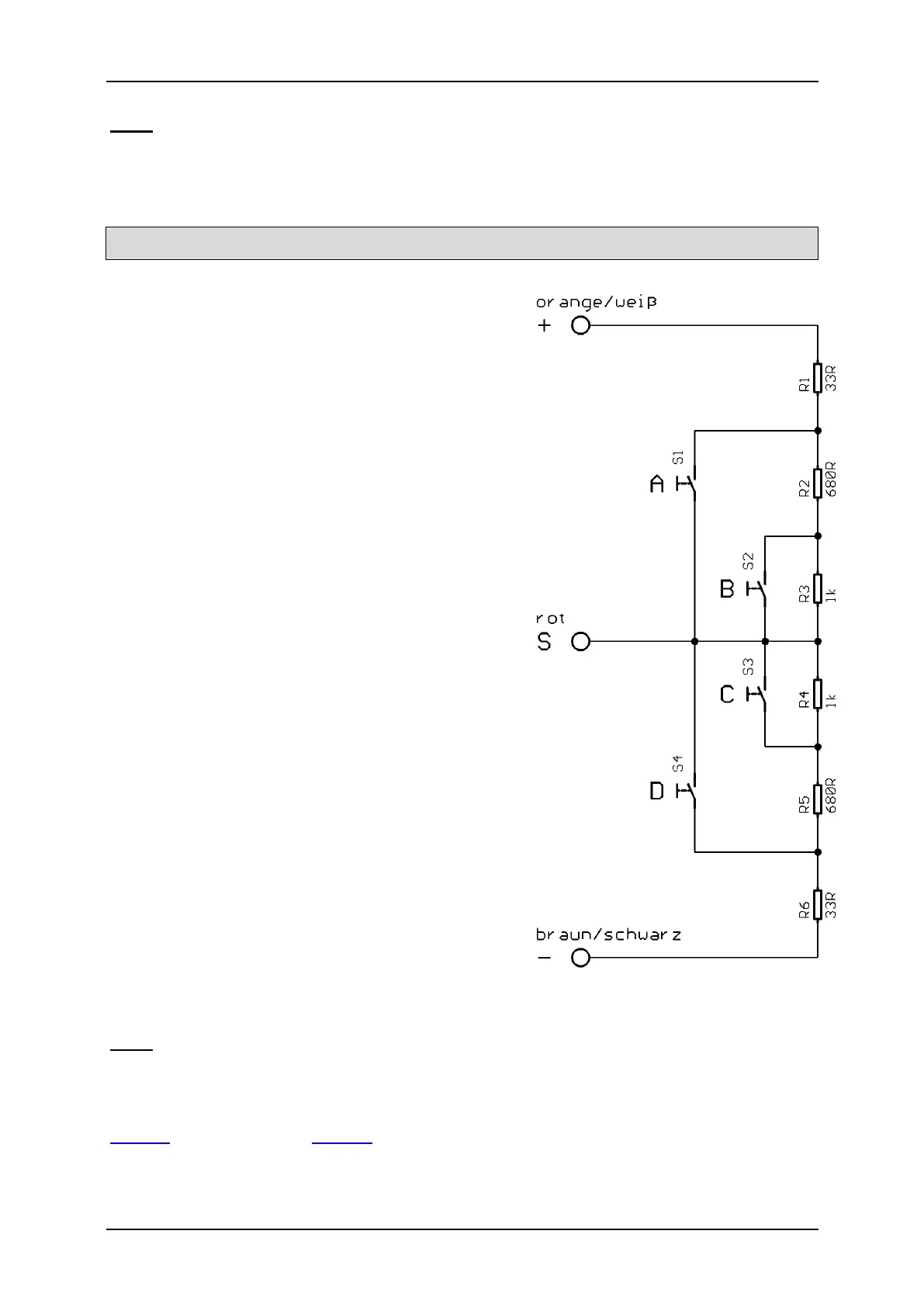
Stick simulation via switches or buttons
To use the functions of the proportional
channels #2 - #8 conveniently, you can simulate
the different potentiometer positions of a stick,
through a simple button press. If you press the
button S1, a stick position is simulated for
position A.
Often the available sticks are already taken by
other functions, but mostly the remote control
has still other free channels. This schematic can
be used for the channels to activate additional
functions.
You need only six resistors and four switches
for each channel (or two reversing switches with
middle position). The small circuit can be easily
built on a strip board.
With the indicated resistors values, this
schematic works with all standard remote
controls. If needed, you can also configure the
thresholds of the five areas in the Sound-
Teacher.
How and where this schematic is connected in
the remote control, is unfortunately differs
according to the radio type.
In some (Robbe/Futaba) remote controls an
additional 68k ohm resistor is neccessary,
which has to be placed in the “S“- wire.
Hint:
Here again, we recommend using the diagnosis to check the constuction.
You can buy this circuit as fully constructed module from us:
SMS-R (for Robbe) and SMS-G (for Graupner and all other manufacturers).
 Loading...